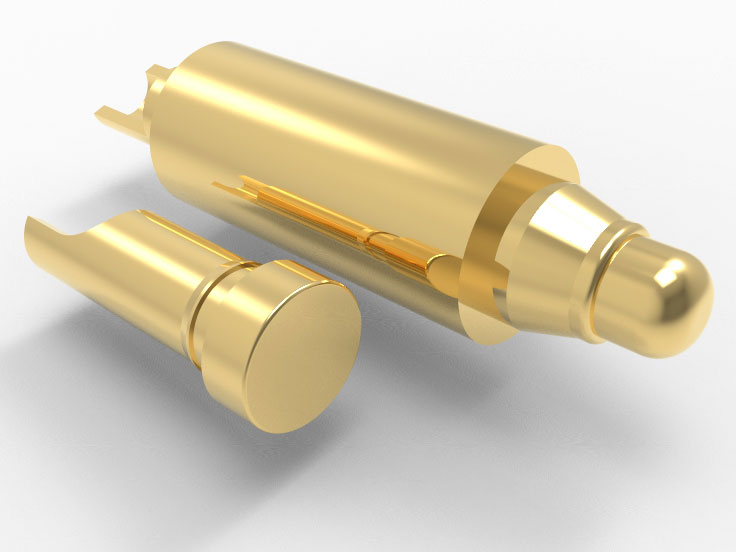
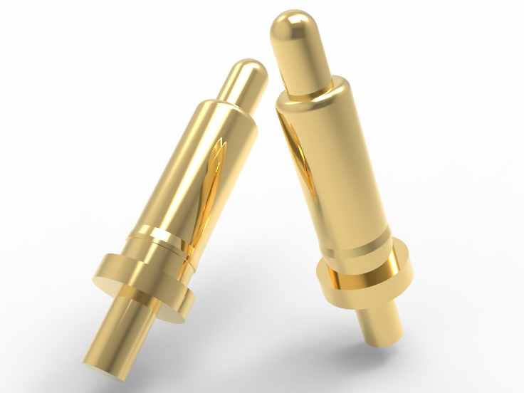
Plunger Material and coating:
BeCu, SK4, 316L, or tungsten steel are commonly used. Beryllium copper has a conductivity of approximately 22% IACS and high tensile strength >1100 MPa, making it suitable for high-frequency plug-in connections. SK4 has higher hardness and wear resistance, making it more advantageous in mechanical impact resistance and high load applications, but its conductivity is slightly inferior. The material selection depends on the current carrying capacity, mechanical fatigue life, and terminal contact pressure.
Gold plating is the most common choice, with a thickness range of 5-30μin. It can achieve stable low contact resistance <50 mΩ and has excellent oxidation resistance. Rhodium (Rh) or ruthenium (Ru) plating is commonly used in high-end wear-resistant designs, with a Vickers hardness of up to 700-1000 HV. It effectively extends lifespan and supports signal and power interfaces.
Spring material and coating:
The spring is made of piano steel wire SWP-B or SUS304, SUS631. SWP-B has high elastic modulus and long fatigue life, suitable for high-frequency compression/release conditions. If corrosion resistance and durability need to be improved, hardened SUS631 stainless steel is the preferred choice. Its yield strength can reach 1250 MPa, suitable for use in high humidity and high salt spray.
To improve corrosion resistance, some springs are treated with electrophoretic coating or inorganic rust proof film. Extend the lifespan of pogo pins and stabilize compression force. Suitable for equipment with electrical interfaces exposed to air or corrosive gases for a long time. It is recommended to verify reliability through the 48 hour salt spray test according to ASTM B117 standard.
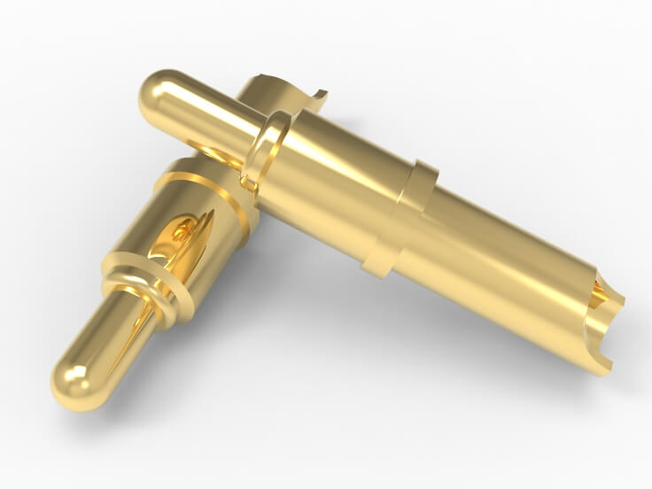
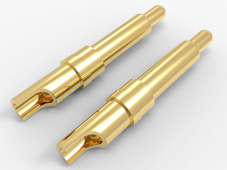
Barrel material and coating:
Generally, brass HBi59 or phosphor bronze is popular. Brass has a high thermal conductivity of approximately 109 W/m·K and good machinability, making it suitable for high current carrying designs. Phospho bronze performs better in terms of elastic recovery and corrosion inhibition. It can use in humid, seawater, or corrosive environments for long time. In actual selection, it is necessary to balance the performance of thermal, electrical, and mechanical aspects.
Usually, Ni is used as the base, followed by gold or silver plating. Nickel plating provides structural strength and corrosion protection. Optimize the stability of the contact interface with the gold plating layer. For high current pogo pins>10A, thick layer tin plating is preferred to enhance weldability and reduce contact thermal resistance. The coating thickness is controlled within the range of 80-150 μin, which meets the requirements of industrial welding processes.
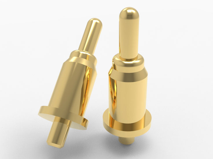
Tail pin material and coating:
C3604 brass or phosphor bronze materials are commonly used, which have good weldability and strength. In stress testing, it is required that the pull-out force of the solder joint exceed 1.5kg to ensure the reliability of the solder joint in wave soldering or reflow soldering. Thermal conductivity and wetting of matching pads are key evaluation indicators.
The surface is usually gold-plated, and the thickness is often the same as that of the needle tube. Can have good compatibility with solder and prevent the formation of oxide film. High end pogo pins adopt a nickel plated bottom layer before gold plating to enhance the strength and shielding performance of solder joints. Suitable for high-speed signal transmission or high current parallel transfer environments.
SMT mounting type of high current pogo pins:
Suitable for highly automated PCBA production lines, fixed to the PCB surface through reflow soldering. The pad design must comply with the IPC-A-610 standard to ensure welding stability and low impedance of electrical connections. Recommended for medium to high-density modular connections with current demand ≤10A.
Through Hole Vertical Mount of high current pogo pins:
The Pogo Pin pin passes through the PCB and is fixed by wave soldering. Provide excellent mechanical strength and stable conductivity. Suitable for repeated plugging and high vibration environments. The pull-out force of the pin can reach over 20N, and the resistance to plugging and unplugging can reach 100,000 times.
Right Angle Through Hole of high current pogo pins:
Suitable for designs with limited space and lateral connections, the needle body is perpendicular to the PCB at a 90 ° angle. Welding should control the amount of tin to prevent shadow effects and ensure the integrity of the current path. Commonly used for side plug connections between communication equipment and rack mounted modules.
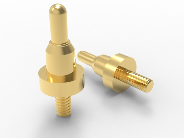
Threaded fixed type of high current pogo pins:
The base is threaded and fixed to metal/plastic components through a screw structure. Paired with copper pillars or heat dissipation components, the structure is sturdy and has thermal stability under high current (>30A). Recommend using M2 or M2.5 standard threads for global replacement.
Snap Fit Mount of high current pogo pins:
Plastic buckles or metal spring clips are directly inserted into the product shell without the need for welding. Pay attention to the temperature resistance of the buckle structure, PA66 material can withstand temperatures up to 125 ° C. It prevents loosening caused by long-term thermal expansion and contraction.
Press Fit of high current pogo pins:
Press into PCB or metal base to avoid welding stress and thermal effects, suitable for high reliability connections. Used in industrial computing platforms, the residual stress of crimping should be controlled within 70% of the material yield strength.
Modular assembly type of high current pogo pins:
The probe is encapsulated in a standard module housing, which can be quickly replaced and maintained, and is used for high-end automatic testing systems. Select modules with positioning and guiding structures to improve insertion and extraction accuracy and contact consistency. The error should be controlled within ± 0.05mm or even ± 0.02mm.
Inlaid injection molding of high current pogo pins:
Embedding Pogo Pin into plastic structure during injection molding process provides strong overall protection and durability. Used in industrial or medical environments that require water proof connectors. Ensure probe sealing and mechanical integrity, up to IP67, IP68 water proof.
Magnetic-assisted type of high current pogo pins:
Combining magnetic positioning to improve contact accuracy and automatic alignment capability. Used for device docking scenarios where visual positioning is not possible. The magnetic force is usually controlled within the range of 10-30mT to ensure stable adsorption without hindering mechanical rebound and contact stroke.
Self-locking fixture type of high current pogo pins:
Fix the probe with an adjustable locking fixture for temporary wiring during the R&D and testing phases. This structure facilitates quick replacement and position adjustment. The contact impedance of the fixture should be controlled below 20mΩ to ensure the accuracy and repeatability of data acquisition.
Thermal Performance and Temperature Rise of High Current Pogo Pins
Location of heat source of high current pogo pins:
The main heat source of the high current Pogo Pin is located in the contact area between the needle body and the spring. Due to the concentration of current and high contact resistance, significant Joule heating is generated at this location. Under continuous current above 10A, the temperature rise in this area can exceed 45°C. Accurate modeling and heat flow path control are required.
Typical thermal resistance structure of high current pogo pins:
The thermal resistance path of Pogo Pin mainly includes: contact thermal resistance, axial thermal conductivity impedance of the pin body, thermal conductivity of the welding area, and environmental convection heat dissipation. The overall thermal resistance is approximately 10-20°C/W, depending on the structure and material. The upper limit of temperature rise per unit power is determined.
Johoty’s thermal rise control design:
Johoty adopts a multi-point gold-plated contact design to reduce local contact thermal resistance. At the same time, high thermal conductivity copper alloy with a thermal conductivity of over 300 W/m·K is selected as the material for the needle body. Design an efficient heat conduction path inside the shell to achieve stable performance output with a thermal resistance of less than 8 °C/W.
Relationship between current density and temperature rise:
Johoty conducted an experiment to test a 1.5mm diameter Pogo Pin at a current of 20A. The temperature rise at the contact area is about 30°C, which is about 17% lower than the market average for products of the same specifications. The temperature rise control mainly benefits from the optimization of internal heat flow distribution and the design of stress compensation structures.
Thermal fatigue reliability testing:
Our high current pogo pins have undergone 1,500 cycles of 10A on-off testing. Contact resistance variance is <10%, and the temperature rise fluctuation is controlled within ± 3°C. The thermal fatigue failure mode is mainly related to stress accumulation in contact with the shrapnel. Effective suppression has been achieved through material tempering and surface treatment.
FAQ
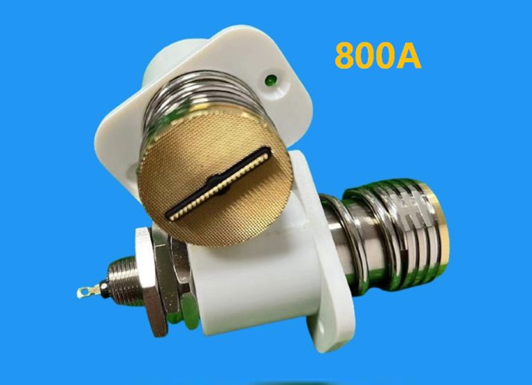
What is the Maximum Current of Johoty’s High Current Pogo pins?
Johoty’s high current pogo pins are designed to support a maximum current of 1200A. By using beryllium copper gold plating and precision CNC machining, we ensure that each Pogo Pin operates continuously at 120 ℃ for 4 hours with a temperature rise not exceeding 25 ℃. They have long-term reliable electrical connectivity to meet high load current transmission.
How Long is the Lifespan of High Current Pogo Pins?
Johoty’s high current pogo pins have undergone strict testing for current and spring force, lifespan is up to 500,000 cycles. We use wear-resistant materials, gold plating, and optimized contact surfaces. It can minimize wear and ensure excellent electrical performance and long-term stability.
How to Ensure Electrical Stability of High Current Pogo Pins?
Johoty conducted rigorous resistance, conductivity, and anti-interference tests for each high current pogo pin. Through these tests, we ensure that the electrical connection is stable and will not cause electrical faults due to overheating, vibration, or external factors, thereby providing high-quality current transfer.
What is Material Selection for High Current Pogo Pins?
Our high current pogo pins are gold-plated beryllium copper or stainless steel, which can withstand high current loads and reduce heat generation. The coating uses corrosion-resistant gold and palladium, which can resist moisture and oxidation, and is stable and reliable. Meanwhile, our materials comply with RoHS, REACH too.
How can High Current Pogo Pins Solve the Challenges in High Temperatures?
For high temperature, we have used thermal diffusion technology in the design, which can effectively dissipate heat and avoid the decrease in current carrying capacity. We also use high-temperature resistant insulation materials to ensure stable operation in large temperature fluctuations.
How to Customize High Current Pogo Pins?
Johoty can provide personalized customization and design suitable high current pogo pins based on customer needs. We can provide customized solutions in terms of size, shape, impedance, material, and current to ensure each pogo pin fully meets your requirements.
 +86 13590816656
 +86 13590816656