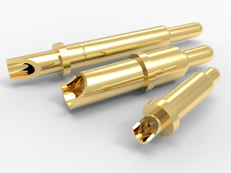
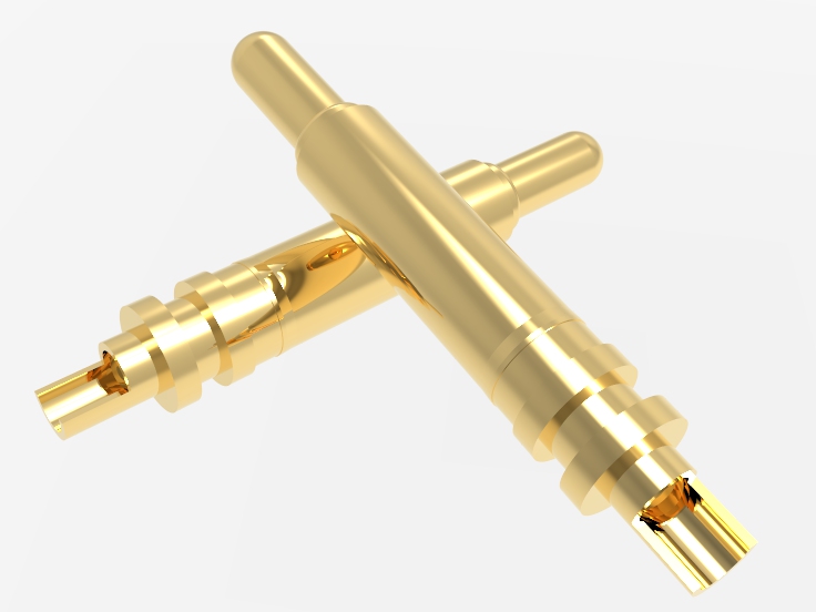
Barrel
Barrel are usually made of brass C3604, C2680, or phosphor bronze (C51000). Brass has good conductivity and mechanical processing properties, with a conductivity of about 23-28% IACS. Phosphobronze has higher elasticity retention and fatigue resistance. The conductivity is about 15-20% IACS, and the fatigue resistance is improved by about 20-30% compared to brass.
Both can be matched with nickel and gold electroplating layers without significant potential difference, and can be in long-term contact. The applicability depends on the balance requirements between conductivity and mechanical stress. Phosphorus bronze is more suitable for vibration environments or structures with high insertion and extraction cycles.
Spring
The mainstream choices are music wire (SWP-B), spring steel, and stainless steel (SUS316, SUS304). SWP-B has strong toughness, with an elastic modulus of about 206 GPa and a tensile strength of up to 1600 MPa. SUS304 has an elastic modulus of about 190 GPa and a tensile strength of about 1,000 MPa, but its corrosion resistance is better than SWP-B. The SWP-B after heat treatment has stronger elasticity retention and is suitable for high-frequency operation.
It can withstand over 500,000 cycles of elastic fatigue. SWP-B is prone to corrosion in high humidity or salt spray environments and requires external nickel/gold coating to improve stability. SUS304 may not be electroplated, but it is not suitable for high load spring applications.
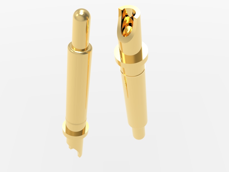
Plunger
Beryllium copper (BeCu) and brass are commonly used, and stainless steel (SUS303) can be selected as a secondary material. Beryllium copper combines high conductivity and mechanical strength, with a conductivity of 45-60% IACS and a tensile strength of up to 1,200 MPa. Stainless steel has low conductivity (about 2-3% IACS) and is suitable for situations that only require structural support and do not participate in signal transmission.
BeCu has no electrochemical corrosion risk with gold, nickel, and tin electroplating layers, and can maintain long-term stable contact When cooperating with SUS303, attention should be paid to increasing the contact resistance. BeCu is suitable for applications that require high signal integrity and long load cycles.
Finishing
The typical surface treatment combination is: nickel bottom layer (4-5μm)+gold surface layer (0.1-2.0μm). Low cost methods such as tin plating can also be used. Gold plating: The surface resistance can be as low as ≤ 15 m Ω, and the contact resistance change rate is less than 5% after up to 500,000 insertion and extraction cycles. Nickel plating: provides wear-resistant protection and anti-corrosion barrier, and is the foundation layer for all surface treatments. Tin plating: Good conductivity but prone to oxidation, suitable for one-time or low-frequency contact occasions.
Nickel has good compatibility with most substrates such as metallic copper, BeCu, phosphor bronze, etc. When the gold layer is in direct contact with the signal needle, a low resistance and high stability connection can be achieved. Tin plating is not recommended for high-speed or high-frequency signal transmission needs.
Flat Tip: PCB end face, test point. Large contact area, suitable for pressure stable scenarios. The stroke is usually controlled within 0.3-0.5mm, customizable, and the contact resistance is often below 30mΩ.
Rounded Tip: Suitable for metal pads and micro bumps. Strong adaptability and reduced risk of damage. Connectors commonly used for frequent plugging and unplugging have an average lifespan of over 10,000 times.
Sharp Tip: Puncture of oxide layer surface and coating layer. Strong breakdown ability, suitable for penetrating non-conductive films, with a penetration depth controlled at about 0.1-0.3mm to avoid damaging the underlying layer.
Concave Tip: Spherical solder joints, BGA spherical surfaces. Automatic centering improves contact reliability. Commonly used for micrometer level tolerance matching, with contact resistance fluctuations controlled within ± 5mΩ.
Blade Tip: Solder wire, bare wire contact. Wire scraping contact, suitable for wire harness testing, recommended contact pressure ≥60gf to prevent virtual connection.
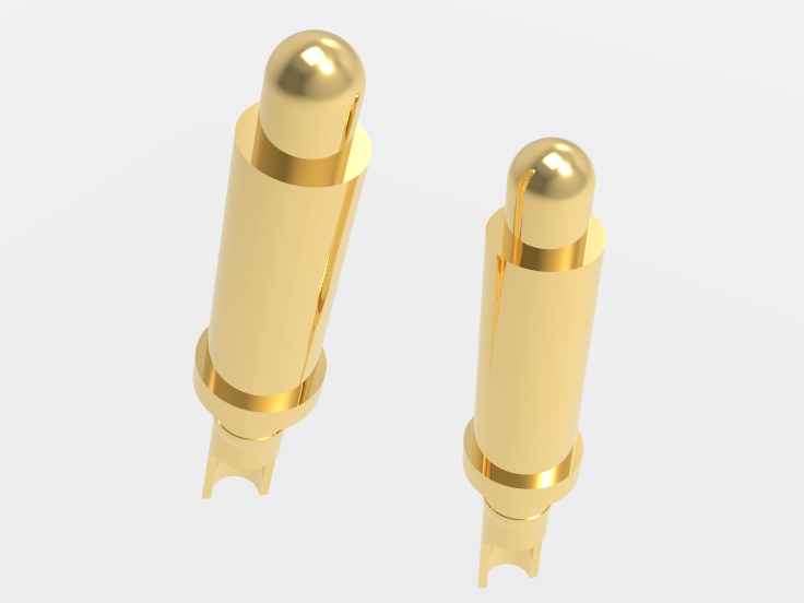
Dome Tip: Slightly uneven surface. Distribute pressure evenly to avoid point contact erosion. Suitable for vibration environment and maintain contact stability.
Fork Tip: Lead assembly, PIN pin surround contact. Multi sided contact enhances clamping force. Used for high-frequency plugging and unplugging scenarios, with lifespan test data >20,000 cycles.
Post Tip: Through hole, for needle fit. Strong directionality, suitable for coaxial connection structures. It is recommended to have a tolerance of ± 0.03mm to match the diameter of the male plunger.
Ball Tip: Sloped solder joints, uneven contact surfaces. freely self-adjusting contact, with an angle tolerance of ± 10°, is commonly used for complex structural plate to plate connections.
Slant Tip: Local coating edges, micro test points. Improve initial contact success rate, suitable for automated probe positioning. The adaptation accuracy requirement is ≤±0.05mm.
Installation of Solder Cup Pogo Pin:
Point Soldering: Low frequency signal, low current application. The structure is simple and suitable for manual welding/small batch assembly. Suggest controlling the tin dots within the diameter range of 0.8-1.2mm. Reliability is evaluated according to the IPC-A-610 standard, with a typical contact resistance stable at <50m Ω.
Cable Insertion + Solder Reinforcement: Medium current transmission (<5A). Improve mechanical pulling force, suitable for multi strand cables (AWG 28-22). The tensile test value is greater than 20N, and the bending resistance after termination is about 2.1 times better than that of pure welded structures.
Embedded Crimping: High speed assembly, automated production line. No welding process, it is recommended to use double wall insulated wire in the crimping area for high process consistency. The typical pull-out force is greater than 25N, and the conductivity stability is more than 10% better than similar soldering schemes.
With Fixing Holes: Load bearing scenarios, high current paths. Combined with mechanical fixation using screws or rivets, the seismic resistance level of the structure complies with MIL-STD-810G. The long-term flow capacity is stable at 10-50A, suitable for high-frequency plugging/high load modules.
Socket Integration: Modular and replaceable system. Easy to maintain and replace components, with an average plug-in life of >30,000 cycles and contact impedance fluctuations of<± 5mΩ, suitable for high reliability scenarios such as medical and aviation.
FAQ
How can solder cup pogo pin improve connection stability?
Solder cup pogo pin provides stronger elastic contact force, ensures long-term stable connection. It helps minimize poor contact risks. High quality materials make contact points more durable. Stable electrical contact prevents signal loss. Precise structure makes contact more firm and reliable.
How does solder cup pogo pin perform in high temperatures?
Johoty’s solder cup pogo pin performs well at high temperatures. The material has high heat resistance and isn’t easily deformed. It can maintain stable electrical contact to ensure equipment operation. Suitable for high-temperatures of electronic devices. Under high temperature, connection remains high reliable.
Is solder cup pogo pin suitable for different sizes?
Solder cup pogo pin offers multiple size options to meet different devices. Adjustments can be made according to circuit board space. Adapt to multiple designs to meet different requirements. Accurate dimensions and specifications ensure accurate connections. Suitable for customized projects and small-scale production.
Is it difficult to install solder cup pogo pin?
Solder cup pogo pin is easy to install for automated production. It can be installed quickly and save labor time. The design is simple for our clients, it is easy to locate. Even complex circuit boards can be quickly adapted. Reduced complexity of traditional connections.
How does solder cup pogo pin perform in high vibration?
The solder cup pogo pin can maintain stability in high vibrations. Its structural design provides sufficient contact force. High elasticity ensures contact continuity. Can effectively prevent disconnection caused by vibration. Suitable for industrial and automotive electronic devices that require vibration resistance.
 +86 13590816656
 +86 13590816656