Johoty’s Services of Surface Mount Pogo Pins
Sample surface mount pogo pins: Complete manufacturability assessment within 24 hours and provide sample BOM and DFM opinions within 48 hours.
Delivery cycle for surface mount pogo pins: Standard model sampling takes 3 working days, with shipment within 14 working days.
Sample processing accuracy guarantee: Coaxiality tolerance of surface mount pogo pins is controlled within ± 0.02mm. Standardized test report for surface coating thickness can be traced back.
Testing methods during the sampling stage: standard electrical continuity, initial impedance, insertion and extraction force, and stroke curve testing, with full process data recording.
Minimum Order Quantity (MOQ): MOQ for standard models or customized structures is 3,000pcs, Johoty also supports customers with < MOQ. Meet customers’ R&D and small batch import needs.
Mass production quality control system: Implement ISO 9001 quality management system, cooperate with customer PPAP documents and FAIR reports.
Consistency and lifespan testing: Each batch of spring force, lifespan cycle >10,000 times, and high/low temperature aging are randomly inspected, and providing third-party verification data.
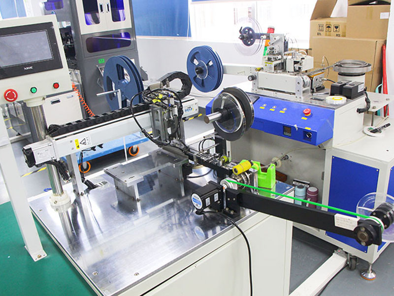
Delivery capability: The monthly production capacity can reach 5 million units, and the fastest delivery time for general structures is 3 days. Customized parts can be completed in bulk within 2 weeks.
Logistics solution: Default DHL/UPS/FedEx for European and American customers. Provide multiple trade terms FOB/DDU/DDP/EXW, with complete export documents.
Sample logistics efficiency: The delivery time for samples from laboratories in the United States/Germany/Netherlands is 5-8 days, with AWB tracking number and customs declaration certificate attached.
Business and technology docking mechanism: Business/technology docking is followed up by engineering and CFT managers with over 10 years of experience. Direct support from engineers (including structural/electrical).
Communication language and cycle guarantee: Supports submission of all English materials and conference communication. Provide written technical feedback and executable solutions to all customer requirements within 48 hours.
Click: More Catalog
Performance Test of Surface Mount Pogo Pins
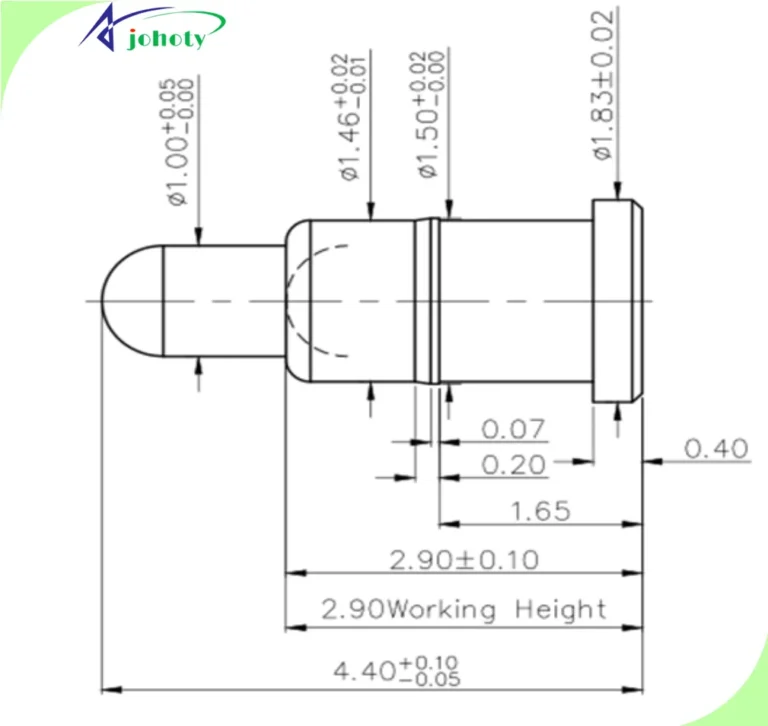
Spring stroke consistency test: detects the reset accuracy after compression to the working height and release, with an error controlled within ± 0.05mm. This surface mount pogo pin can be well adapted for automated probe holder and precision module assembly.
Terminal resistance stability measurement: Under a load current of 2A, the contact resistance remains stable at <50mΩ, and the resistance change throughout the entire stroke does not exceed ± 5%. Verify the reliability of power/signal hybrid transmission.
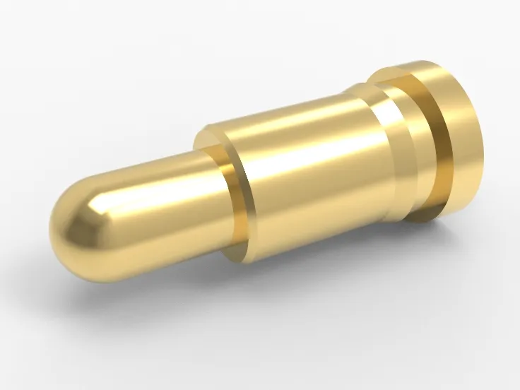
Contact integrity test under lateral stress: Johoty’s maintains conductivity on surface mount pogo pins with ball plunger tips under a lateral force of 0.3N. Simulate the electrical continuity after PCB bending or module offset under extreme operating conditions.
Thermal shock response performance of solder pads: No welding cracking or metal fatigue after 1,000 thermal cycles at -40℃ to+85℃. The T&R packaging structure of SMT has strong stability.
Vertical compression fatigue life test: After continuous compression for 50,000 times, the elastic attenuation is less than 10%, meeting the life requirements of high-frequency signal circuits and mechanical switch modules.
Coating wear assessment (through end face SEM analysis): The area with a gold plating thickness of ≥0.1μm remains intact at >85% after 100,000 insertions and removals. The highest gold plating layer reaches 50μm, and surface mount pogo pins ensure long-term corrosion resistance and conductivity of the contact layer.
Soldering consistency test: All PIN pins have a wetting angle of less than 30° in the 245℃ ± 5℃ soldering test. Ensure consistency of end face welding during reflow soldering process.
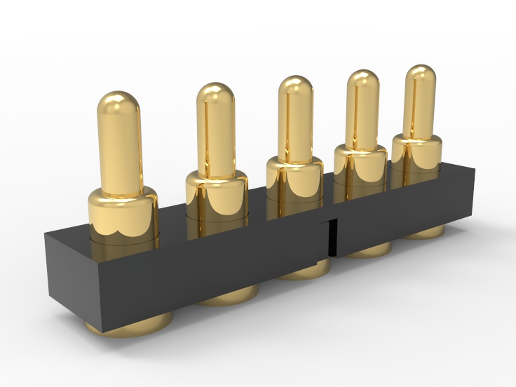
Verification of installation height tolerance: After soldering the surface mount pogo pins, measure their total height from the PCB surface to the top, with a height difference of ≤±0.05mm within the batch. It can demonstrate excellent performance in high-speed pogo pin connector array packaging.
Click: More Catalog
Customization of Surface Mount Pogo Pins
Customization capability for compression stroke range: The effective stroke range can be set from 0.10mm to 1.20mm according to application requirements. Match the spacing and compression fit logic of different modules.
Contact force accuracy adjustment capability: supports setting within the range of 0.05N~1.5N, with an error control of ± 10%. Stable connection from weak signal access to medium current transmission under pressure.
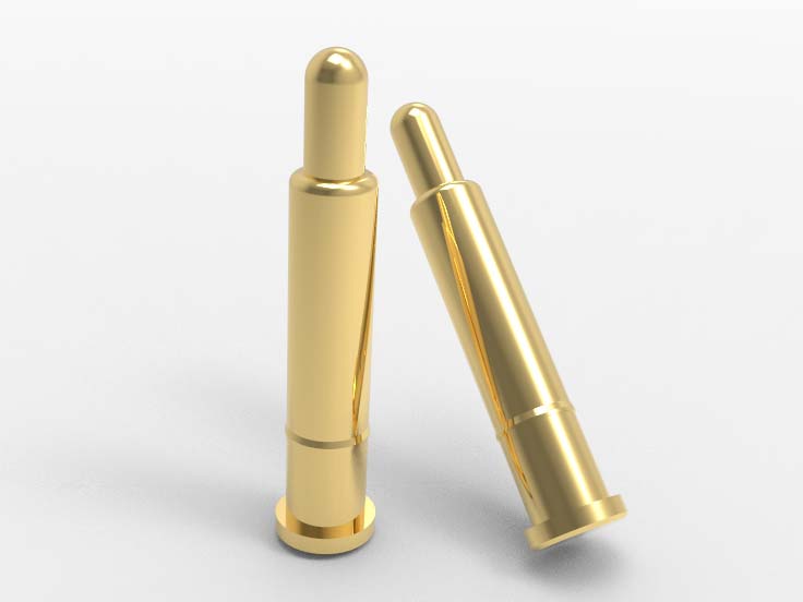
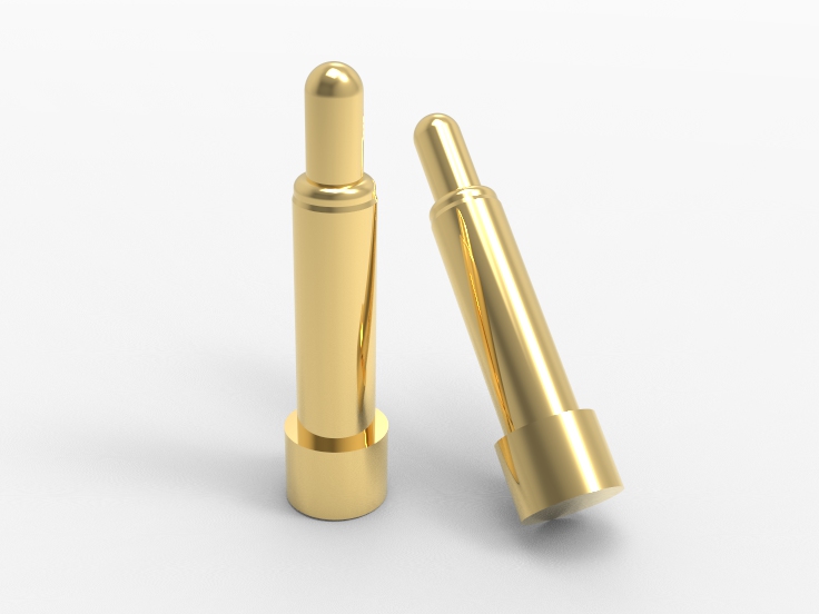
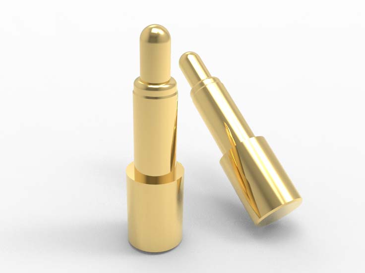
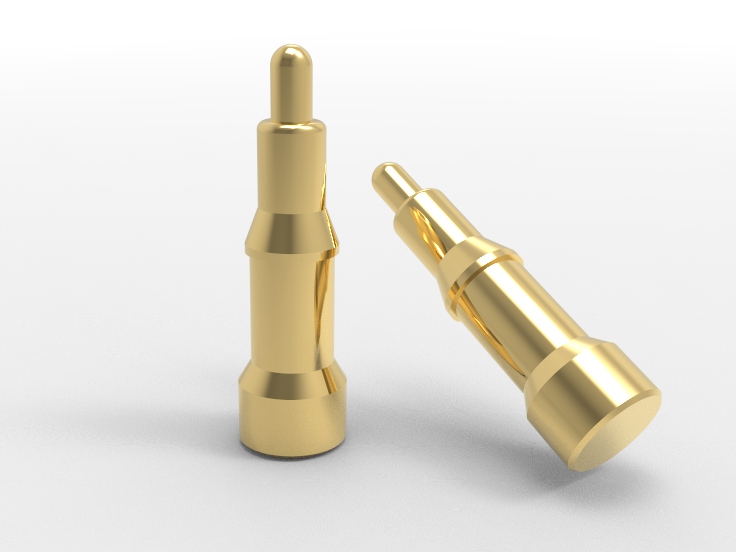
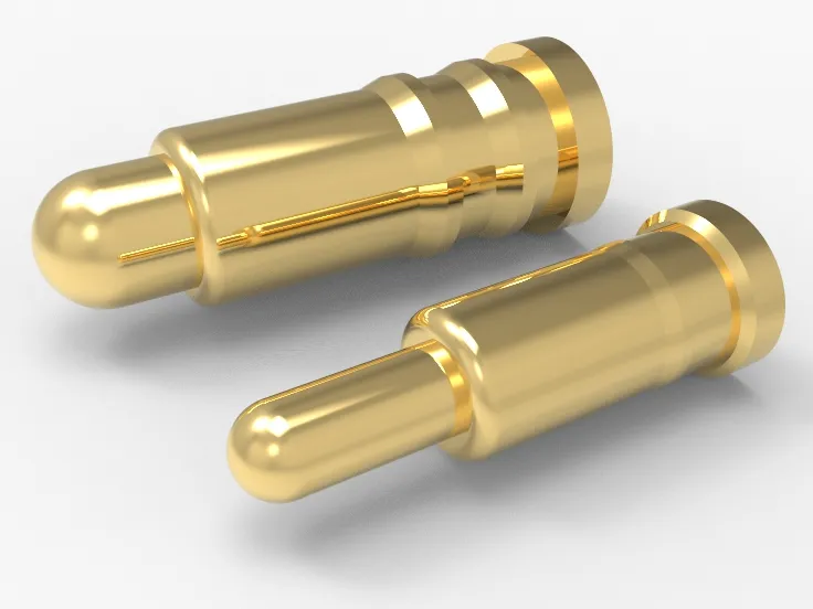
Optional configuration of plunger tip shape: provides various end geometry forms such as flat head, conical head, ball head, inclined head, and blade mouth. Satisfy various docking structures such as coated contacts, solder pads, cables, etc.
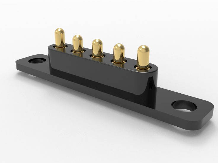
Customization support for tail structure: Multiple SMT tail designs: flat tail, side mounted, clip on, and spring welded tail can be selected. Different pad layouts and reflow requirements can be met.
Adjustable material combination capability: Barrel copper alloy, spring steel SWP-B, nickel gold coating, nickel silver, nickel palladium platinum gold composite combination can all be configured. Support structural design optimized for conductivity, wear resistance, and cost.
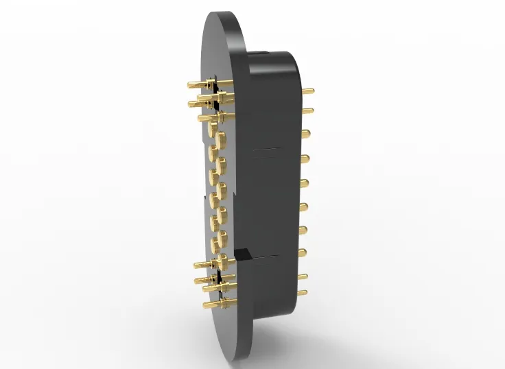
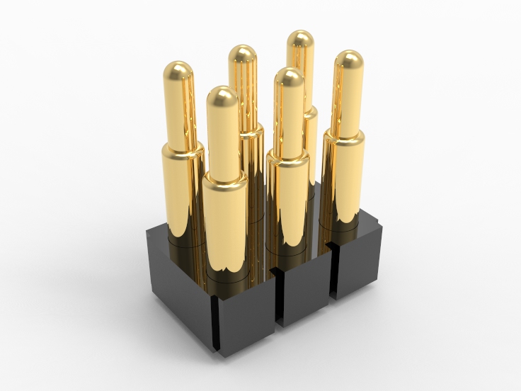
Pitch layout can be defined: Surface mount pogo pins support any center to center distance array layout above 1.00mm. Meet high-density interface requirements such as pogo pin connectors, probe modules, and testing fixtures.
Customization of PIN number and arrangement direction: Supports horizontal/vertical/matrix arrangement, with strict control over the size of the fully encapsulated internal structure. Space constrained integrated design can meet the needs of product engineers.
Surface treatment compatibility assessment: Based on customer’s solder pad or plating process, adjust the pogo pin surface treatment plan in coordination. Avoid electrochemical corrosion, tin whisker growth, or coating peeling.
Response to irregular structure sampling: It can quickly model and sample according to special packaging (L-shaped, T-shaped, embedded slot), with a response time of <48 hours.
Click: More Catalog
FAQ
What is the maximum rated current of surface mount pogo pins? In a single pogo pin structure, it typically supports a maximum continuous current of 5A (at 20℃). The pogo pin connector with multiple pin connections in parallel can expand the load path.
Does it support standard SMT process mounting? Of course, all end tail designs are compatible with industrial grade lead-free reflow soldering curves. Tail flatness <±0.05mm, suitable for fully automatic mounting lines.
How to control the consistency of plunger height after compression of surface mount pogo pins? The top height tolerance of pogo pins under full load compression state is ≤±0.05mm. It is suitable for the consistent conductivity requirements of parallel spring loaded connectors.
Will contact resistance of surface mount pogo pins increase after long-term use? After 10,000 life cycles, the contact resistance of surface mount pogo pins does not increase by more than 15%. The contact interface remains stable and is suitable for high-frequency mating systems.
Do surface mount pogo pins experience structural displacement under vibration or drop conditions? The plunger and barrel of surface mount pogo pins are designed with interference fit or embedded compression structure. After passing the IEC 60068-2-6 vibration test, there was no looseness displacement.
 +86 13590816656
 +86 13590816656