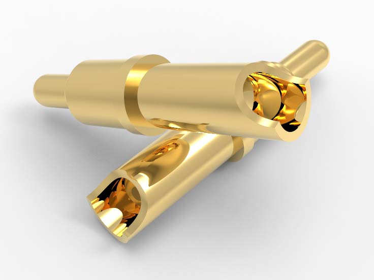
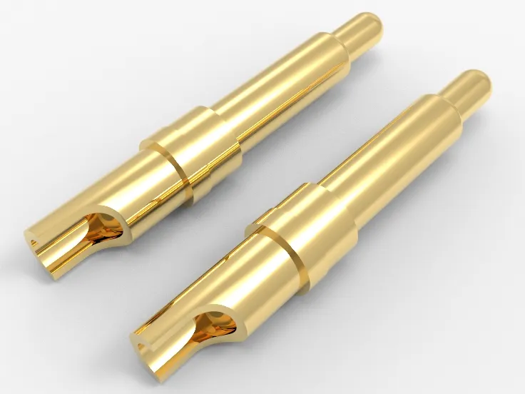
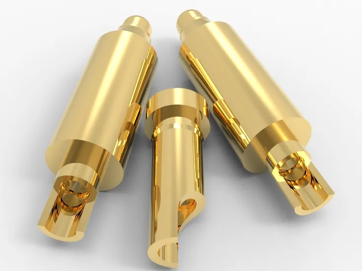
Johoty’s Services of Spring Loaded Pins
Spring loaded pins for sampling: supports three sampling methods: drawing sampling, sample sampling, and joint verification of functional scenarios, all of which provide traceable drawing approval.
Sampling response cycle: Within 48 hours after drawing confirmation, a sampling production order will be issued, and within 72 hours, samples (excluding special customization) will be sent out.
Sample consistency of spring loaded pins: All samples were 100% tested for resistance, voltage drop, and elasticity curves.
Material traceability: The spring loaded pins material, coating, and cup head welding section can all provide batch original material inspection reports (COA).
Quality standards: Spring loaded pins comply with MIL-STD-202 (vibration, impact), IEC 60512 (contact resistance, lifespan), RoHS/REACH compliance.
Delivery time: Standard delivery time is within 5 working days, customized specifications do not exceed 15 working days, and independent production line scheduling is set for high priority projects.
Minimum order quantity (MOQ): Standard spring loaded pins have a minimum order quantity of 5pcs for sampling, and customized parts have a minimum order quantity of 3,000pcs. Allow mixed batch trial production batch processing (per order processing).
Sample logistics: default DHL/UPS/FedEx air freight door-to-door, exporter code and customs HS CODE, and attached in the shipping documents.
Formal bulk shipping logistics: supports various conditions such as FOB to meet the actual needs of different factories’ receiving/assembly links.
Delivery materials: All formal delivery documents include sample packaging diagrams, measured contact resistance values, and torque/compression force testing data sheets.
Contact person qualification: The entire process is coordinated by a technical project manager with a background in mechanical/material/engineering. Have experience in engineering drawing recognition, FAI analysis, and DOE.
Project docking mechanism: Support Team/Room/WhatsApp/Email project cycle follow-up. Regular stage review/failure analysis feedback to ensure technical closure.
Click: More Catalog
Performance Test of Spring Loaded Pins
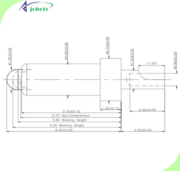
Contact resistance testing: measured under standard load compression ≤50mΩ, stability evaluated through 10,000 cycles of testing and data curve attached.
Elastic curve calibration: Provide a complete force response curve within the range of 1.00mm to compression limit, supporting ± 5gf tolerance verification.
Travel stability test: Conduct 10,000 reciprocating strokes at the rated maximum compression displacement without any jamming or structural failure records.
Coating wear resistance test: After completing the spring loaded pins according to ASTM B571 standard, at least 80% of the effective contact area should be free of substrate exposure.
End welding reliability test: The tail of the solder cup is welded with lead-free tin material for tensile testing, with a minimum holding force of >10N.
High frequency mating life test: For rapid contact, the contact impedance drift should be ≤5% after ≥20 times/minute and 10,000 times of plugging and unplugging.
Spring loaded pins salt spray test: Conduct a 48 hour salt spray test according to IEC 60068-2-11, and the contact resistance change rate after the test is less than 10%.
Vibration and impact testing: Complies with Method 204D (vibration) and Method 213B (impact) requirements of MIL-STD-202G standard.
Continuity detection of conductivity: Spring loaded pins achieve stable conductivity throughout the entire compression stroke, with a response time of ≤10μs and no interruption points.
Hot cycle test: Alternating 100 cycles in an environment from -40℃ to+85℃, the contact performance of spring loaded pins does not degrade.
Dimensional stability and repeatability verification: high-precision laser measurement of the total length, tolerance range, compression displacement, etc. of spring loaded pins. Attached is a batch deviation chart.
Click: More Catalog
Customization of Spring Loaded Pins
Compression stroke: Supports free setting of stroke parameters within 0.20mm to 4.50mm, matching different module tolerances.
Elastic specification: Provides a force value configuration of ≥5gf, meeting low triggering sensitivity and high voltage connection stability.
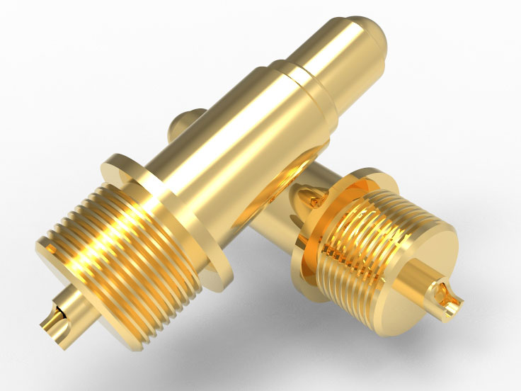
Outer diameter and total length: Customized ≥0.50mm barrel diameter and 7.00mm to 12.00mm total length, suitable for different installation cavities.
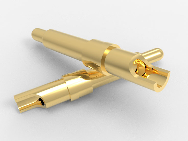
Solder cup tail size: The diameter, depth, and wall thickness of the tail welding cup can be designed according to the customer’s wire diameter and welding equipment orientation.
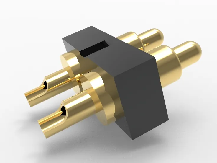
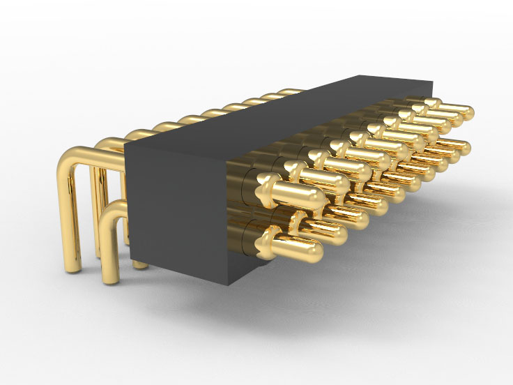
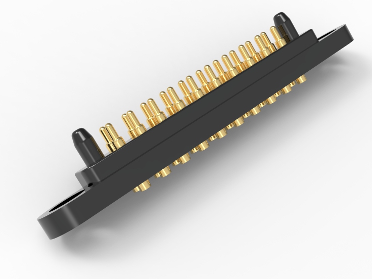
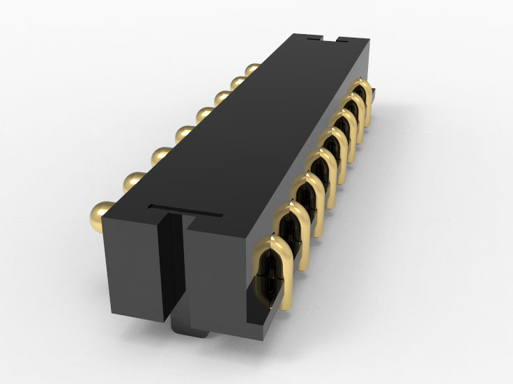
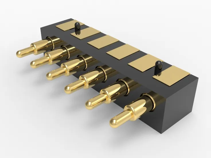
Diverse installation structures compatible: supports 3 common solder cup designs, compatible with metal/plastic seats and housing components.
Flexible material selection: brass, beryllium copper, stainless steel, etc. can be selected to meet the requirements of conductivity, corrosion resistance, and mechanical strength.
Plating combination: Supports gold plating, silver plating, nickel plating, and composite plating solutions. The thickness can be set from 1 μ in to 200 μ in to ensure contact performance.
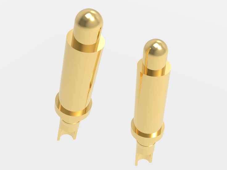
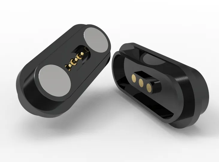
The shape of the contact head supports drawing development: the shape of the contact head can be customized according to the actual scenarios of customer point contact, surface contact, or plunger tip detection.
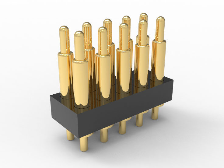
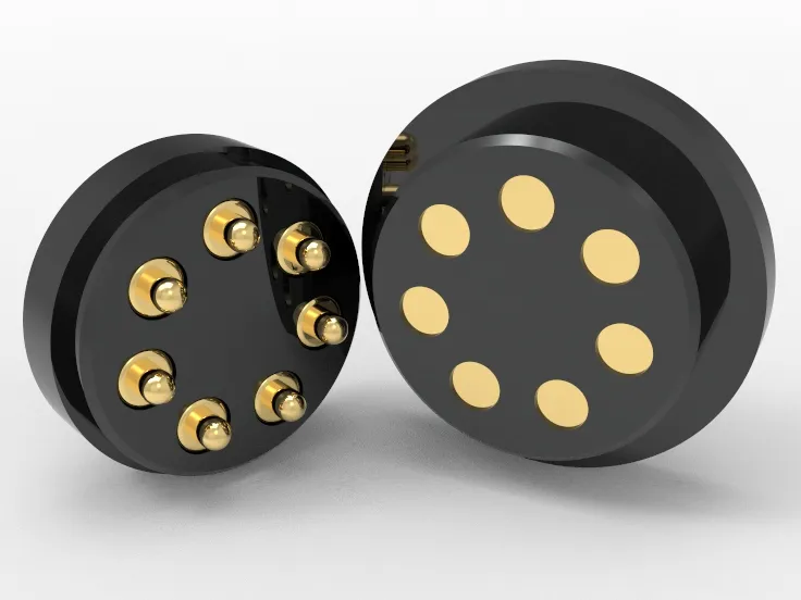
Multi PIN component packaging capability: Supports integrating multiple spring pins into custom pogo pin connector, providing corresponding module packaging and 3D drawings.
Multi temperature zone working ability verification: Thermal deformation and performance stability design can be carried out between -55℃ and+150℃ according to customer operating conditions.
Signal and current mixing requirements: Supports spring loaded pins to carry signals, currents, or a combination of both. The maximum current passing through a single spring loaded pin is 50A.
Reverse development of customer samples: 3D modeling, material analysis, mechanical property restoration, and development drawings can be completed based on physical samples.
Click: More Catalog
FAQ
Are spring loaded pins suitable for cable welding structures? Yes, the solder cup tail is designed specifically for manually or automatically soldering cables. High contact stability and repeatable assembly. Spring loaded pins are used for cable to board connections or internal electrical extensions within modules.
Does Spring loaded pins meet the mechanical travel and contact retention requirements for pogo pin lengths greater than 7.00mm? Satisfied, pogo pin length greater than 7mm can achieve greater compression stroke and displacement buffering. Suitable for large stacking tolerances or board spacing adjustments to enhance system compatibility margin.
Do spring loaded pins support high-frequency plugging or dynamic contact? Support, the spring loaded pin structure has been tested to withstand more than 10,000 mechanical cycles. Spring loaded pins are commonly found in electrical interfaces with high requirements for frequent plugging, vibration environments, or dynamic contact.
Can Spring loaded pins be compatible with modular connectors or custom fixture platforms? Compatible, the solder cup tail is easy to integrate with various module connection solutions. The pogo pin length supports fixture designs for different platforms, facilitating rapid verification and batch integration.
Can Spring loaded pins provide different coating, pogo pin length, or elasticity parameters as needed? Of course, Johoty can provide it. We can customize the gold plating thickness, spring force specifications, and pogo pin length configuration based on contact current, insertion force, or corrosion environment requirements. When designing spring loaded pins, we support complete technical parameter matching.
 +86 13590816656
 +86 13590816656