Johoty’s Services of Spring Loaded Pogo Pins
Sampling spring loaded pogo pins:
Full process engineer led: After the customer provides drawings or application scenario explanations, feasibility analysis and packaging confirmation are completed within 48 hours. Support industrial format integration such as STEP, DWG, IDF, etc.
High matching specialized fixture sampling: Ensure axial flatness of>10mm spring loaded pogo pins <0.02mm, suitable for sinking plates or back welding structures.
Full process transparent tracking: The process nodes include initial pogo pin assembly, spring assembly, sleeve welding, and coating quality control, with visual tracking and photographic feedback for each step.
Free FMEA analysis: If there are poor electrical connections or PCB warpage compatibility issues during the matching trial assembly of the sample, a complete FA report will be provided.
Quality standards:
The verticality deviation of spring loaded pogo pins is ≤±0.03mm. The overall consistency is ±0.05mm.
Spring life >50,000 cycles @ 2.0A. Consistency of coating thickness Ra<0.1μm.
Through consistency testing of 0.5μm gold + 3μm nickel electroplating, supporting RoHS/REACH files.
Perform mechanical fatigue testing according to IEC 60512-5-2, with SGS report attached.
Delivery of spring loaded pogo pins:
The standard sample shall be sent out within 5 working days, and the initial batch for customized mass production shall not exceed 14 working days.
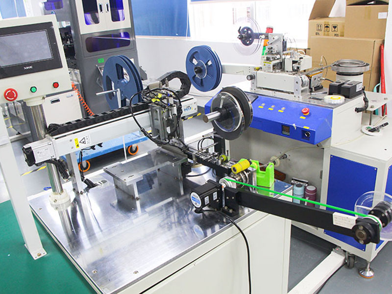
We have our own precision CNC lathe and assembly production line, with parallel support for sampling and small batch production.
Urgent demand support for 48 hour high-speed samples (limited to structural components).
The delivery schedule will be provided and updated by the project responsible engineer in the form of a Gantt chart.
MOQ (Minimum Order Quantity):
The sample stage supports starting from ≥10pcs.
The standard PIN model MOQ is 200pcs, and the minimum order quantity for customized structural components is 1000pcs.
Structural fine-tuning without the need for mold opening supports a minimum order quantity of ≤500pcs.
Logistics method of spring loaded pogo pins:
Default FedEx Priority international express delivery, with 5-8 deliveries in Europe and America. Include logistics costs when quoting.
We can provide DHL/UPS multi option quotation comparison, with HS code and inspection number attached.
All shipments include batch tracking numbers, material certificates, and factory quality inspection forms.
Qualification of liaison person:
Assign pogo pin connectors/precision hardware engineers with over 10 years of experience to project level clients for coordination.
If it is a medical, military, or aviation customer, it can be equipped with personnel with ITAR experience or engineers holding IPC-A-610/IPC-6012 certification.
Support technical communication in both Chinese and English, and arrange real-time video review and parameter agreement if necessary.
Click: More Catalog
Performance Test of Spring Loaded Pogo Pins
Mechanical performance testing of spring loaded pogo pins:
Insertion force test: According to the axial load standard, ensure a linear displacement response between 0.2 and 1.5N, with a deviation control of ± 5%.
Compression stroke stability test: The length change of the sample with a stroke ≥3.0mm under 100 full strokes shall not exceed ±0.03mm.
Rebound consistency: During 500 compression release cycles, the rebound height of 100% batch samples changed by<± 0.02mm.
Verticality/coaxiality detection: The CNC probe is combined with an imaging system to measure the angle error between the pin and the reference plane, which should not exceed 0.5°.
Electrical performance testing of spring loaded pogo pins:
Contact resistance: Test under rated compression force to ensure <50mΩ and temperature drift control <± 5%.
Current carrying capacity: Conventional 3A current test, accompanied by a 10 minute steady-state recording curve, with a thermal rise not exceeding 30K.
Overcurrent tolerance test: Supports 3.5A 60 second current impact to ensure pogo pin material and coating do not melt or discolor.
Signal integrity testing (optional): Provide TDR reflection testing and insertion loss ≤0.5dB@1GHz for high-speed requirements.
Life and fatigue testing of spring loaded pogo pins:
Mechanical life test: >10,000 full stroke compression cycles, detect changes in contact resistance after every 5,000 cycles.
Coating wear test: For samples with a surface gold layer thickness greater than 0.5μm, SEM cross-sectional analysis is performed after repeated compression.
Fatigue curve of spring structure: a tensile tester combined with high-frequency vibration simulation provides a trend chart of spring failure points.
Environmental stress resistance test: Accelerated aging at 85°C/85%RH for 168 hours, with a contact impedance growth rate of <15%.
Welding compatibility and through-hole compatibility testing of spring loaded pogo pins:
Through hole pin soldering stress test: Simulate the PCB warpage after inserting the pin into wave soldering or reflow soldering, ensuring it is ≤0.2mm.
Through hole wettability test: Under the recommended through hole copper thickness and pad coverage, ensure that the solder climb is ≥95% and there is no virtual soldering.
Analysis of the fit gap between pins and PCB hole walls: Combined with actual X-ray tomography, evaluate the radial gap uniformity and solder coating.
Welding residue test: Ion contamination detection before and after cleaning <1.56μg/cm² NaCl equivalent value.
Material and consistency verification of spring loaded pogo pins:
Tensile and hardness testing of metal materials: conducted in accordance with ASTM B348 and GB/T 4340 standards.
Surface plating layer thickness testing: XRF fluorescence analyzer is used to measure the thickness of gold and nickel layers pogo pin by pogo pin.
Batch consistency testing: Randomly sample ≥10pcs from each batch, record deviations and statistical intervals item by item, and attach traceable records.
Salt spray test: NSS has no coating peeling or corrosion spots for 48 hours or above.
Click: More Catalog

Customization of Spring Loaded Pogo Pins
Structural customization of spring loaded pogo pins:
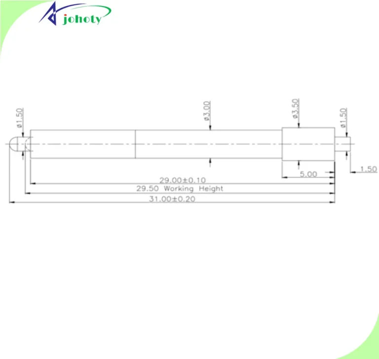
Support precision machining within the range of 10.00mm~70.00mm for full pogo pin length, with a tolerance control of ± 0.05mm.
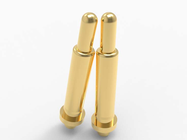
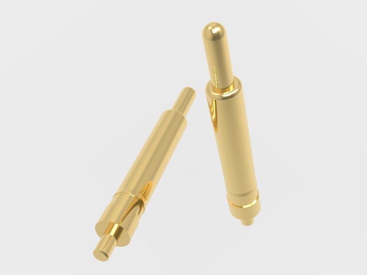
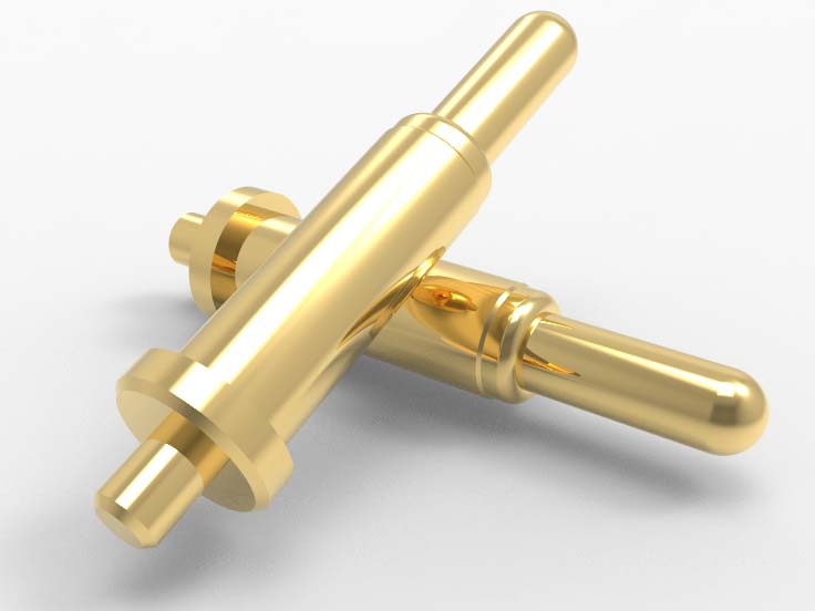
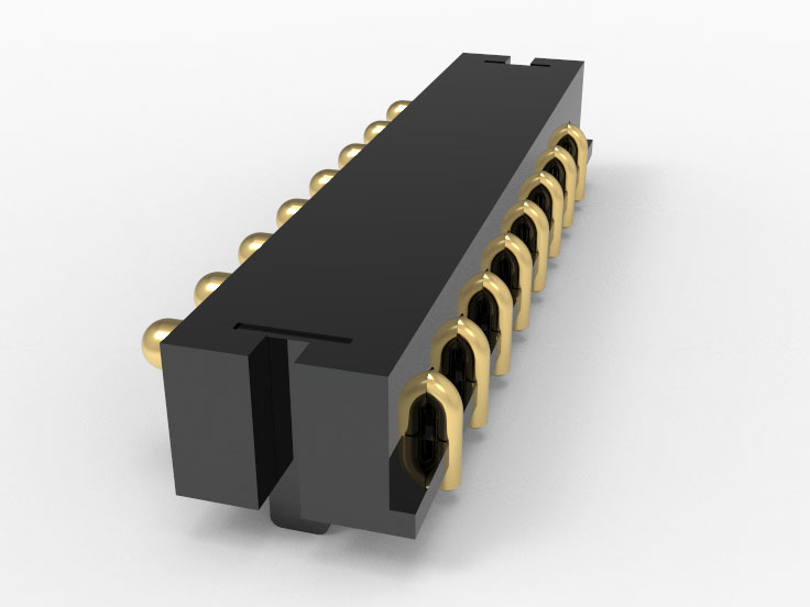
Customizable head structure (round head, blade head, groove head, concave point, spherical surface, ellipse, crown, etc.). Tail form (crimping type, direct insertion type, stepped type, reserved welding position type).
Capable of designing non-standard stroke compression springs, supporting eccentric and double elastic structures.
Support special limit mechanisms or customized multi-stage travel, suitable for pin voltage limiting or floating docking needs.
Electrical and functional customization of spring loaded pogo pins:
Support design optimization for different current specifications (0.5A~10A), including plunger diameter, spring stiffness, and electroplating combination.
Low insertion loss head shape can be customized for high-speed signals and matched with TDR simulation.
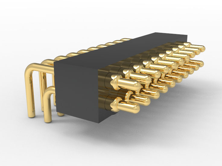
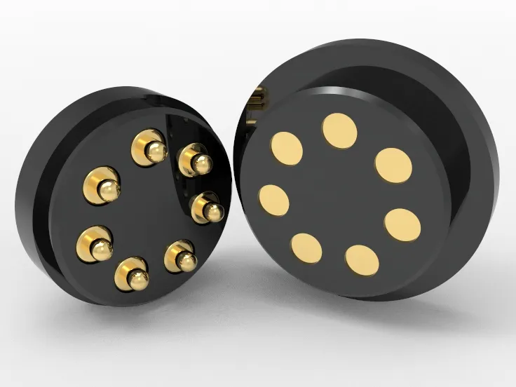
Supports multi-point grounding/multi pin parallel design, suitable for power redundancy or shielding structures.
Having experience in multi-stage spring impedance matching and seismic strategy design, meeting the reliability requirements of medical and military grade.
Through-hole adaptability of spring loaded pogo pins:
The pin diameter and tail fitting section can be set according to the customer’s PCB process to meet the requirements of through-hole insertion with a hole diameter of 0.30-6.00mm.
Support chamfer design on the plugin end to reduce assembly stress and the risk of PCB through-hole damage.
The tail can be equipped with anti stripping rings, limit shoulders, and solder paste coverage positioning areas. Improve welding consistency and matching of through-hole tension.
Process customization of spring loaded pogo pins:
Capable of secondary processing such as turning, grinding, milling, and embossing, meeting the requirements of complex pogo pin end structures.
Surface treatment supports composite coating combinations such as gold plating (0.1 μ m~5 μ m), nickel base, tin layer, and thick copper.
The spring material selection includes SUS304, SUS631, piano wire, and bainitic steel, supporting anti magnetic/high fatigue/directional elastic design.
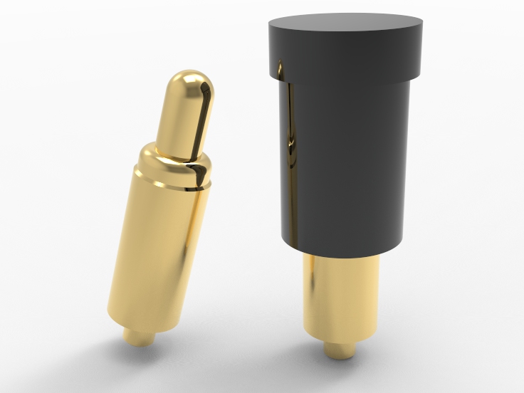
Can be encapsulated in T&R format or Tray format to meet SMT/automatic plugin requirements.
Project docking and response:
The engineering docking is the responsibility of engineers with a design background in precision pogo pin connectors of ≥ 10 years. Familiar with standards such as IPC-2221, IEC 60512, UL1977, etc.
All customized projects must complete feasibility assessments and structural diagram recommendations within 48 hours of project initiation.
We can provide STEP, DWG structural diagrams and analysis reports to support internal simulation and whole machine assembly verification for customers.
If cross departmental technical collaboration is involved, support the establishment of joint project windows. Perform periodic version confirmation and trial production integration.
Click: More Catalog

FQA
Can spring loaded pogo pins be inserted into copper plated PCB through holes ≥3mm without causing board warping or soldering voids?
It can be achieved. We support the design of pin tail step matching, and the size and tolerance control of the insertion section are based on the recommended values of IPC-2222. At the same time, the tail limit structure is used to avoid stress concentration in the welding area, which has been stably applied in 1.60mm thick PCBs.
Can spring loaded pogo pins withstand repeated insertion and extraction or impact vibration without loosening or pogo pin displacement after compression installation?
The matching accuracy between barrel tail and the through-hole is controlled within the range of ±0.02mm. The pressure holding force can reach 50N, and it has passed simulated transportation, drop experiments, and 10Hz~500Hz 3-axis sweep vibration tests. No structural displacement occurs after assembly.
Will continuous power on of 3A or more during full stroke of spring loaded pogo pins cause abnormal heating or spring failure?
can’t. All current path components are made of low resistance copper alloy material and treated with ≥ 0.5μm thick gold +3μm nickel composite electroplating. Under 5A steady-state operation, the heat rise is ≤ 20℃. The selection of springs is based on the optimization of thermal fatigue curves, with no attenuation of force values after continuous power on testing for more than 100 hours.
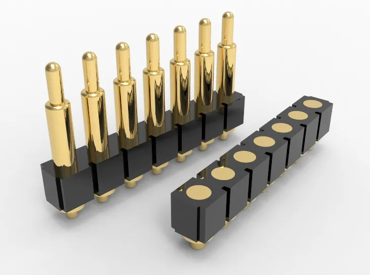
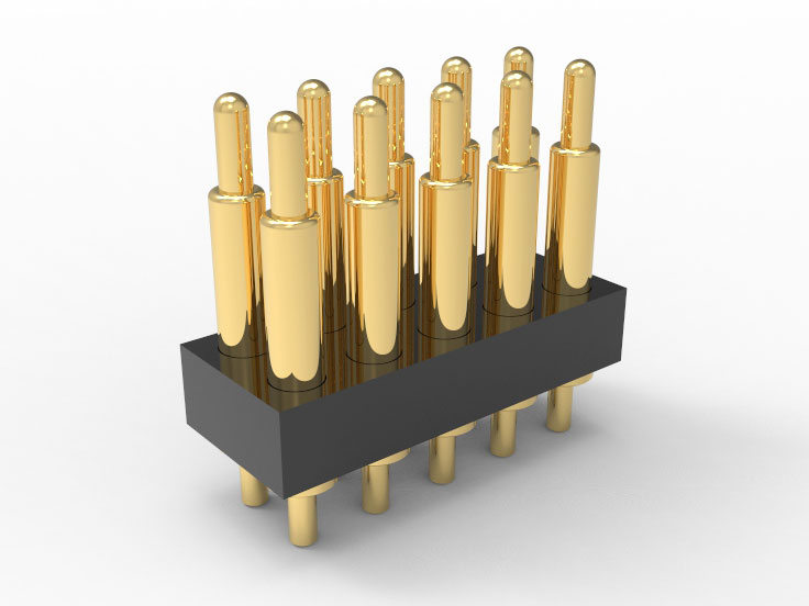
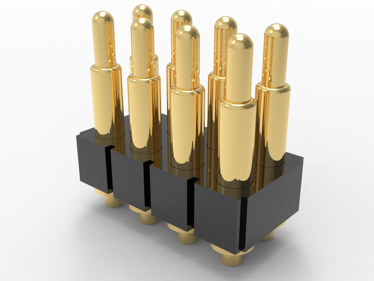
Can multiple Spring loaded pogo pins be modularly arranged and installed to ensure pitch tolerance and end face coplanarity?
Of course I support it. It can be designed as a modular carrier array structure, with a pitch support of ≥1.00mm and a tolerance of <±0.05mm. The coplanarity of the end face is controlled by fixture reference pressing and maintained within ±0.03mm. Suitable for multi-point synchronous contact or board to board elastic connection structures.
Is there a verifiable batch consistency record and material traceability path for spring loaded pogo pins?
Yes. All spring loaded pogo pins are encoded with marked source material, machining, and assembly batch information. Support the export of batch data packages throughout the entire process (including XRF material testing reports, coating thickness reports, and compression fatigue spectra). Meets ISO 9001 and industrial grade traceability system.
 +86 13590816656
 +86 13590816656