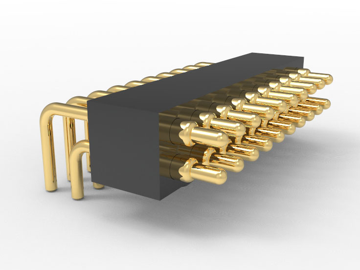
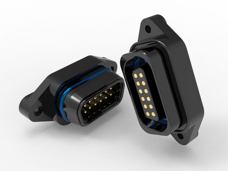
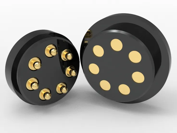
Johoty’s Services of Spring Pogo Pins
Sample spring pogo pins: Start within 24 hours and complete sample delivery within 3-5 days. Support 2D drawing and 3D structural diagram integration. Before leaving the factory, 100% of the samples were tested for pogo pin height, contact impedance, elasticity, and 23 tests.
Quality control: aerospace grade precision standard, barrel cylindricity error control <0.01mm. Contact resistance ≤30mΩ, full inspection and delivery time commitment: standard products will be delivered within 3 days from the order, customized parts will be delivered within 14 days. Simultaneously carry out surface treatment, electroplating, and assembly processes.
Minimum Order Quantity (MOQ): Acceptable samples starting from 5pcs, with no minimum quantity limit for a single sample order. Mass production MOQ 3,000pcs, will flexibly cooperate with customer’s project schedule
Logistics method: FedEx/DHL/UPS global direct delivery, delivery to Europe and America within 5-8 days, default includes shipping insurance and full tracking.
Contact person: >10 years of experience in pogo pin connector industry as an engineer. Familiar with PCB/connector embedding compatibility standards, with IPC/UL/Six Sigma BB certification.
Click: More Catalog
Performance Test of Spring Pogo Pins
Contact resistance stability test: Spring pogo pins have a contact impedance of ≤50mΩ and no significant fluctuations after 10,000 power cycles.
Mechanical life verification: Under the condition of 50% compression stroke, after ≥10,000 cycles, the elastic recovery rate is>98%.
Vertical insertion force test: maximum not exceeding 1.2N, ensuring no micro cracks or copper foil stress damage to PCB through holes.
Consistency testing for maintaining force: Batch fluctuations within ± 10% range, spring pogo pins can meet the stability of automated assembly clamping.
Wear resistance test for through-hole insertion: After 50 cycles, there are no scratches on the hole wall, no transfer of coating, and no tendency for offset insertion.
Electroplating integrity verification: The Au coating thickness is 0.15μm, and there is no pitting or peeling phenomenon after 1000 hours at 85℃/85% RH.
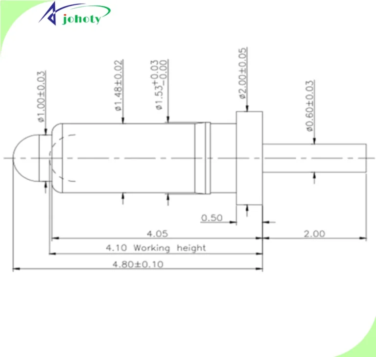
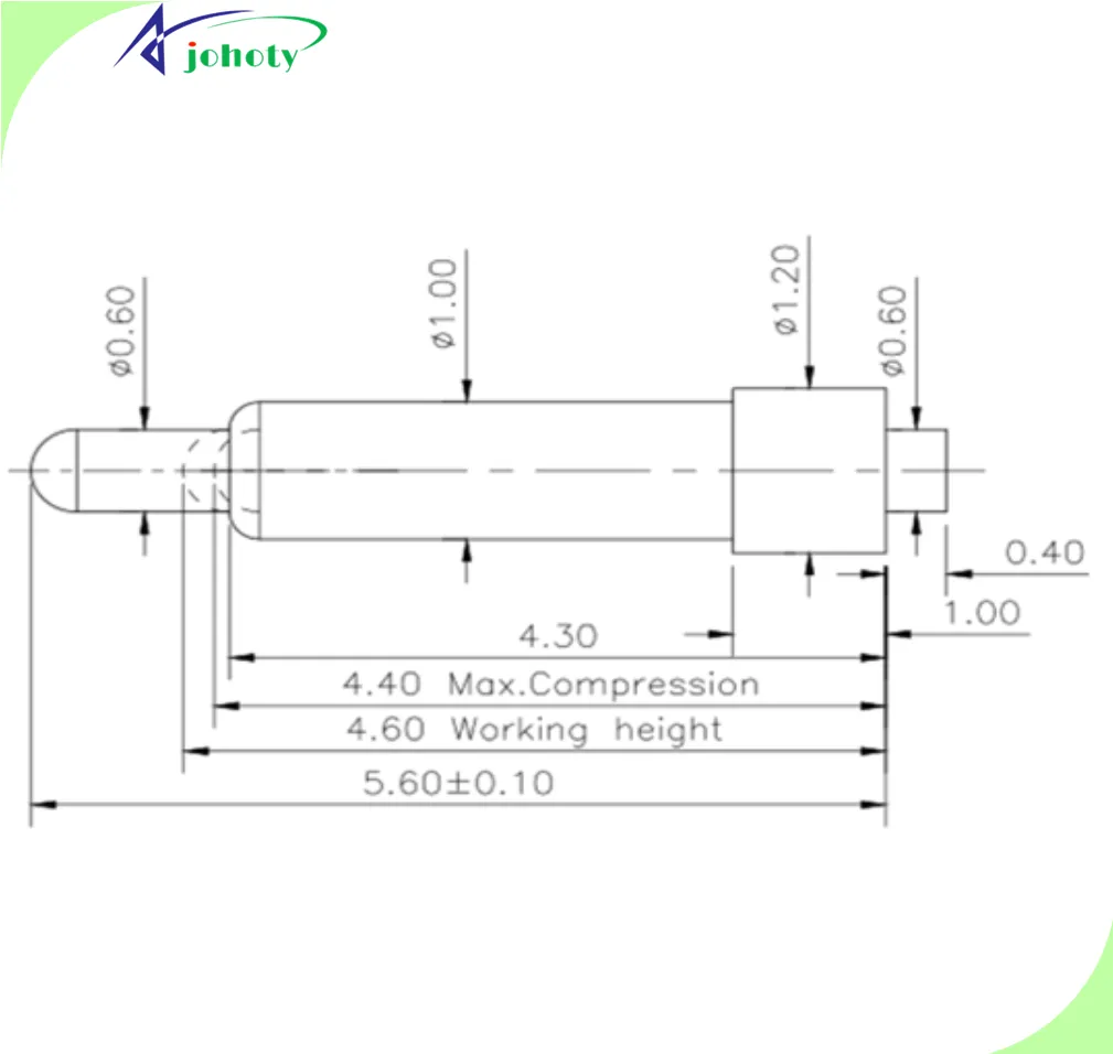
Measurement of work height consistency: Within a tolerance of ± 0.05mm, ensure signal synchronization and voltage balance of the multi-point contact system.
Thermal stability test: After 200 cycles at temperatures ranging from -40℃ to+105℃, the structure and conductivity of spring pogo pins did not deteriorate.
Matching evaluation: Spring pogo pins support a tolerance for through-hole gaps of Φ 0.95-1.10mm, without the need for additional customization of PCB aperture.
Automatic welding compatibility test: After inserting the through-hole, the support force is stable and can withstand the wave peak impact under reflow soldering without displacement.
Click: More Catalog
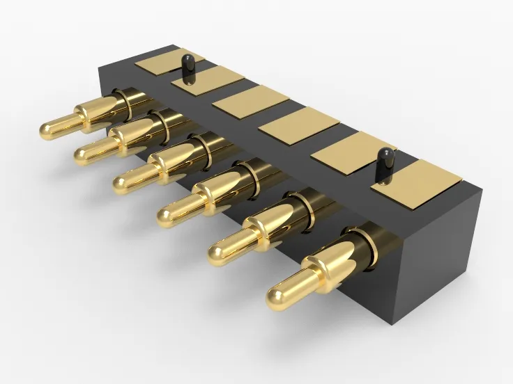
Customization of Spring Pogo Pins
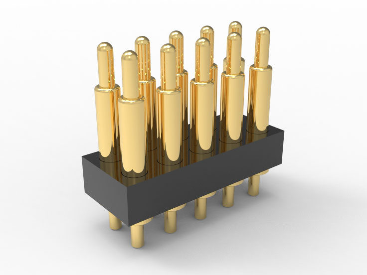
Barrel length fine-tuning capability: supports customization of 0.05mm pitch between 6.00mm and 7.00mm, in conjunction with asynchronous PCB clearance.
Diameter specification adjustable: ≥0.50mm supported across the entire series, matching conventional and non-standard through-hole sizes (including 0.95 ±0.05mm).
The range of stroke can be defined: flexible configuration of compression stroke from 0.10mm to 2.5mm, perfectly matching different elastic requirements and dynamic contact.
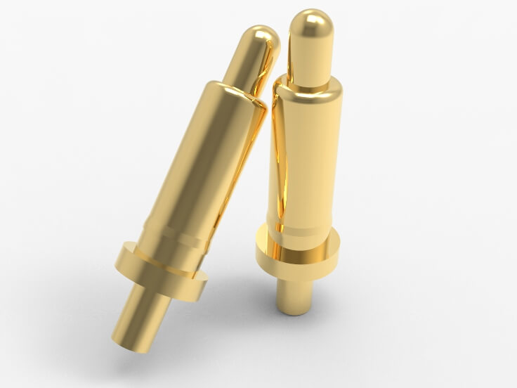
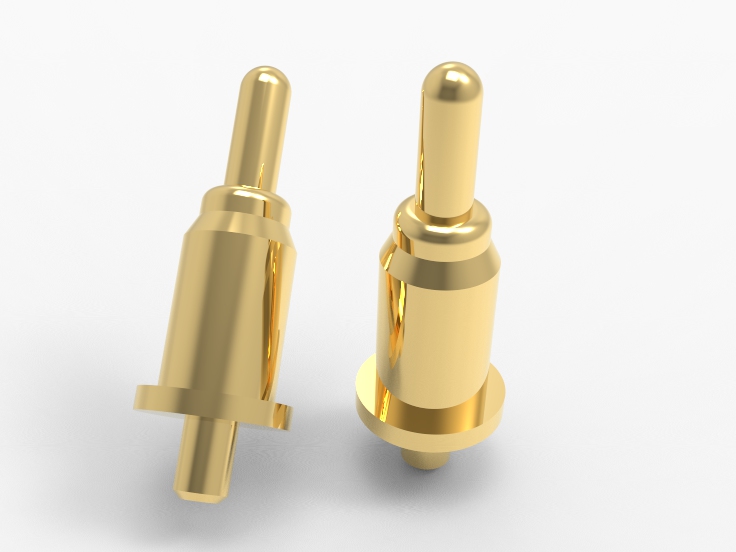
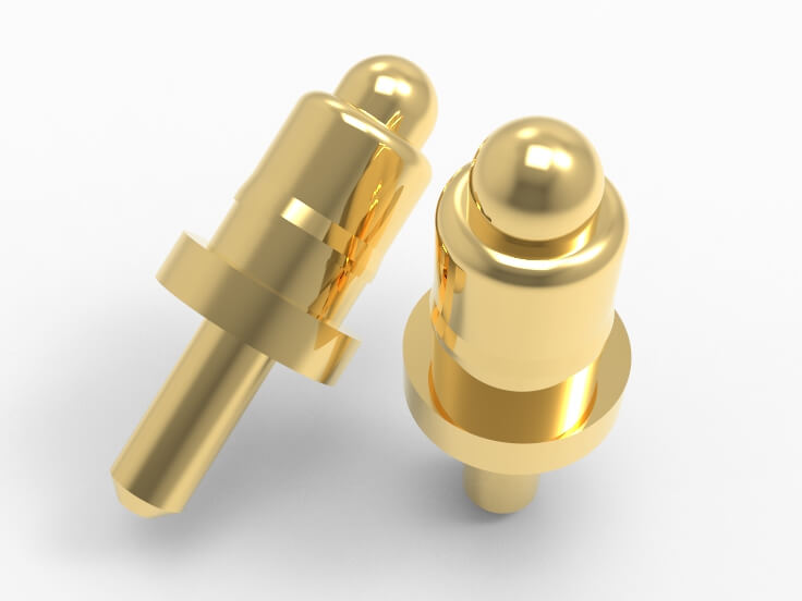
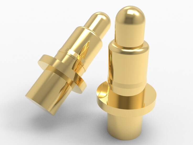
Plumger tip structure can be customized according to the contact interface structure, including ball head, flat head, pointed end, conical surface, and concave surface.
The spring force curve can be adjusted: the initial force and maximum force can be modeled and simulated based on the elastic modulus to meet the vertical pressure threshold control.
Customized electroplating solutions: available in Ni/Au, Ni/Pd/Au, Ni/Pt/Au, or composite electroplating. Adapt to different levels of conductivity as well as corrosion resistance.
Barrel material customization: brass, stainless steel, phosphor bronze are optional, controlling different structural rigidity and thermal expansion coefficients.
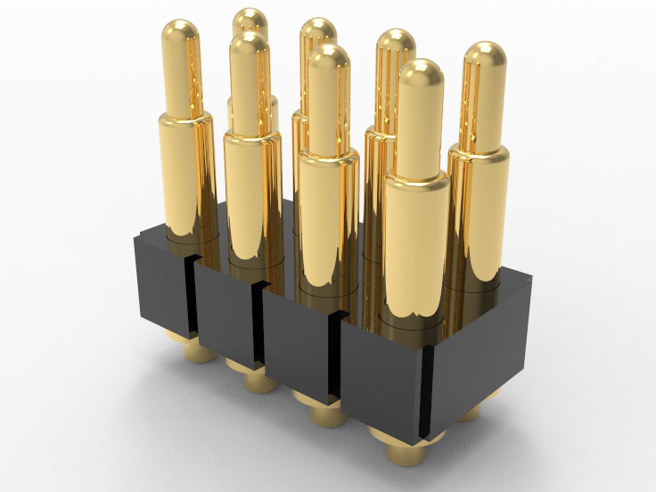
Batch error control capability: Dimensional error ≤±0.02mm. Maintain high consistency and docking reliability when assembling multiple pogo pin arrays.
Cooperate with hole tolerance analysis: support 3D interference simulation report and plug-in friction coefficient modeling, accelerate customer design closed loop.
Click: More Catalog

FAQ
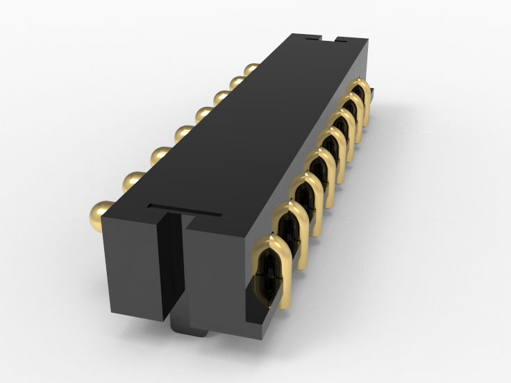
Are Spring pogo pins compatible with through-hole wave soldering & manual soldering? Support, the tail structure can be either soldered or crimped, and the solder resistance of the plating layer has been verified to be non delamination.
Can spring pogo pins work in high temperature/humidity environments for a long time? Sure, after 1,000 hours of aging testing at 85℃/85% RH, the contact resistance has no drift.
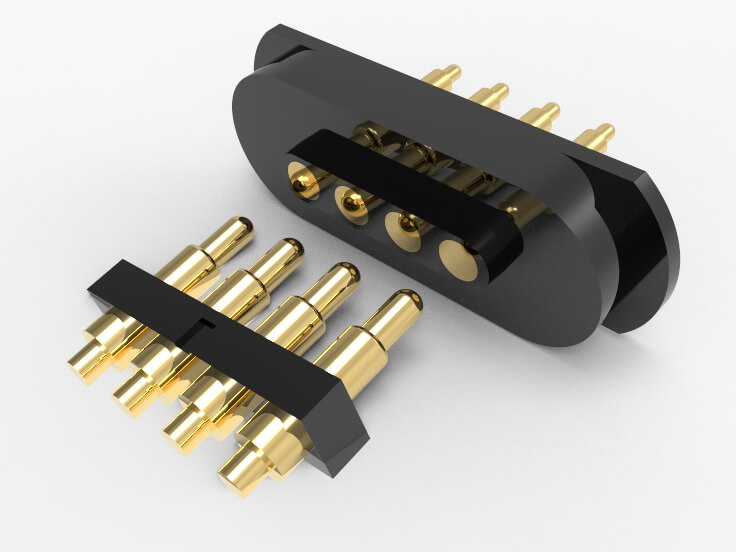
Do Spring pogo pins support dense arrangement of multiple PIN arrays? Support, minimum center distance of 0.95mm, casing wall thickness controlled within ± 0.02mm to avoid interference.
What is the required tolerance range for PCB through-hole? The recommended aperture is 0.95 ± 0.05mm, and the needle diameter can be adjusted in special circumstances to accommodate wider tolerances.
What is the control level of elasticity consistency of Spring pogo pins in mass production? Within ± 10%, the spring force is controlled by the precision of imported winding equipment and undergoes full inspection and screening.
 +86 13590816656
 +86 13590816656