Johoty’s Services of Micro Pogo Pins
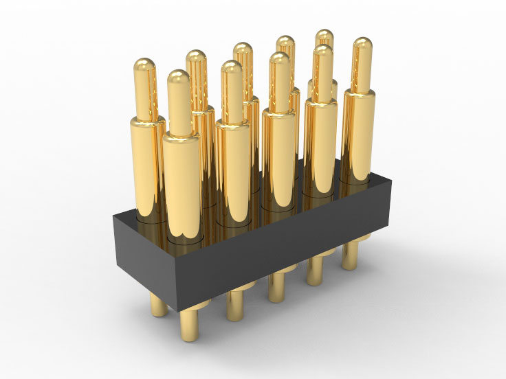
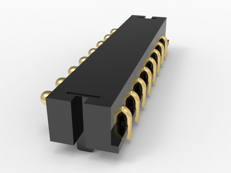
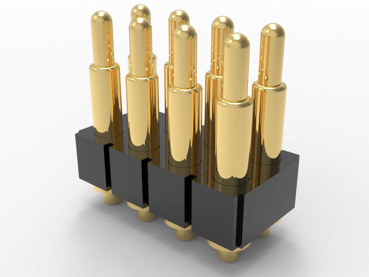
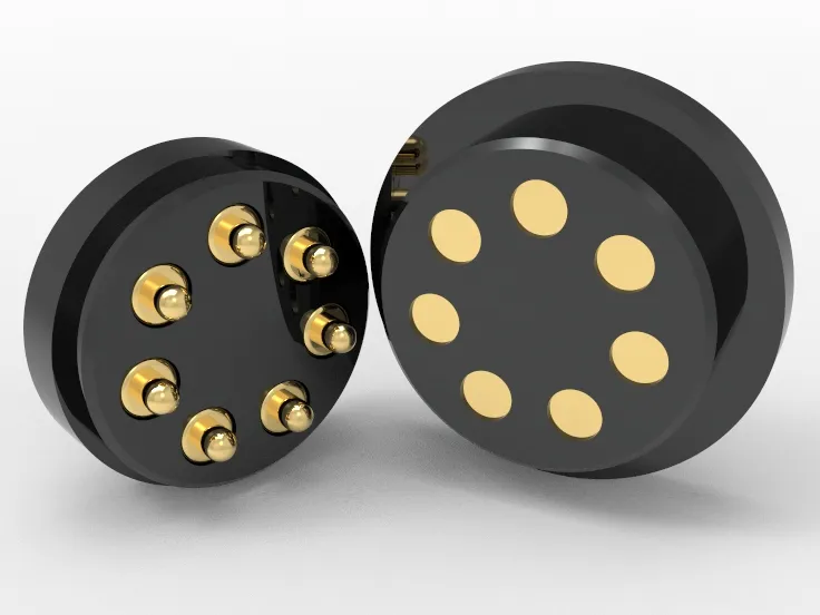
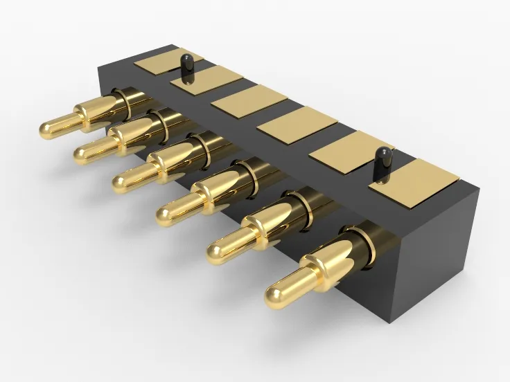
Sample Micro Pogo Pins:
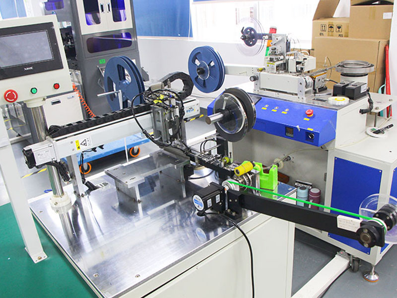
Support customized sampling for 3 or more sets. Complete DFM evaluation, structural drawing review, and 2-week sample delivery within 3 days. Adapt to the fully automatic SMT mounting process and mainstream Reflow technology. Standard configuration with T&R/nozzle proposal and coordinate diagram.
Quality control of Micro Pogo Pins:
The thickness, elasticity curve, and connection stability of the electroplating layer have been verified by IPC-TM-650 and AEC-Q200 standards. Batch supports FAIR and SPC full process traceability. Match vehicle regulations/medical regulations/military regulations requirements. The consistency error control of barrel/insulated ball/spring/plunger is less than ± 0.02mm.
Delivery time for Micro Pogo Pins:
Standard samples can be delivered within 48 hours at the fastest, and customized structures can be completed within 3 weeks. The delivery cycle for the first batch of mass production is stable at 2-3 weeks (supporting early material locking/urgent production scheduling).
MOQ (Minimum Order Quantity):
There is no MOQ during the sampling stage, and the minimum order for small batch trial production is ≥3000pcs. During mass production phase, flexible rolling ordering is supported according to project stages (including BOM lock order/framework agreement mode).
Logistics for Micro Pogo Pins:
Support DHL/FedEx priority service, with direct access to the entire Europe and America from 5 to 8 days. Express projects can be shipped using UPS Saver or a third-party account designated by the customer. All shipments are provided with material proof, ROHS/REACH reports, and packing drawings by default.
Qualification of service personnel:
Frontline docking engineers have an average of over 10 years of work experience, with backgrounds in medical/automotive/communication/consumer electronics. Communicate in English, fully participate in structural design suggestions, material selection, reliability analysis, and FMEA.
Click: More Catalog

Performance Test of Micro Pogo Pins
Electrical contact resistance detection:
Contact resistance ≤ 30mΩ (typical value 18-22mΩ). Stability: The resistance deviation under 10000 consecutive loads is less than 5%. The test is based on IEC 60512-2-1 and MIL-STD-1344A standards.
Consistency test of travel and elasticity curve:
The recommended working distance is 0.15~1.10mm, and the elasticity deviation rate is ≤±8%. 20 samples are taken from each batch for statistical analysis of the relationship between travel and elasticity. The tolerance range for the height of the welding surface after automatic placement matching is ± 0.05mm.
Resistance to welding thermal shock:
Through JEDEC J-STD-020 thermal cycling test (260℃ reflux peak x 3 times), there was no spring performance degradation or structural damage. The welding end coating has no bubbles or cracks.
Mechanical life test:
The plug-in life is greater than 10,000 times, and the critical failure is defined as contact resistance>50mΩ or stroke attenuation >10%. The entire process is loaded according to GB/T 2423.5 and ISO 10373 standards.
High and low temperature shock and wet heat cycle:
Supports wide temperature operation from -40℃ to+125℃, with 10 cycles of wet and heat (85℃/85% RH). The structural components are corrosion-resistant, and the fatigue life attenuation rate of the springs is less than 3%. Test according to AEC-Q200 Rev. D specification.
Microscopic consistency test between Barrel and electroplated layer:
SEM + EDX analysis of the coating structure profile showed that the thickness of the Ni/Au coating was controlled within the range of 80 μ in/10 μ in. Plunger Ra roughness <0.2 μm, full inspection and analysis report issued.
Carrier compatibility and vacuum nozzle stability:
Match the 8mm/12mm load standard (compliant with EIA-481-D), with a coordinate deviation of<± 0.03mm. The success rate of 20 consecutive nozzle tests is 100%, and support temperature rise simulation testing at the feeder end.
Click: More Catalog
Customization of Micro Pogo Pins
Scope of structural customization:
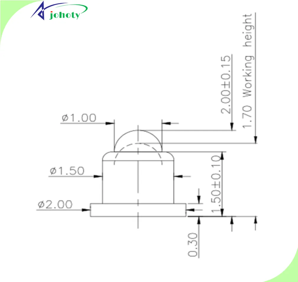
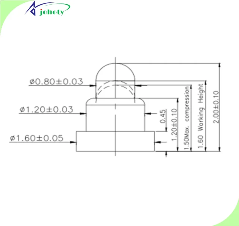
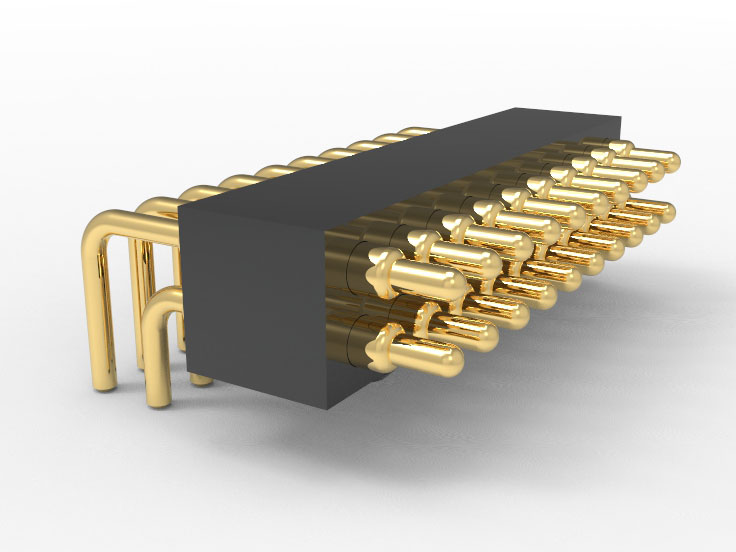
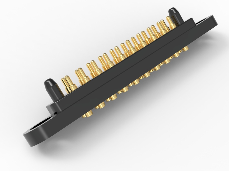
Support customization of needle length from 1.60mm to 3.00mm with any precision, with a tolerance control of ± 0.02mm. Optional single needle/double needle/multi contact structure, with a minimum wall thickness of 0.15mm for the spring chamber, suitable for high-density packaging and wiring restrictions.
Directional design of travel and elasticity parameters:
The adjustable working stroke range is 0.10mm~1.10mm, and the controllable elastic range is 5-120Gf. It meets the requirements of different loads, contact surface pre pressure, and rebound time. Support bidirectional simulation verification of static compression and dynamic scanning.
End design capability:
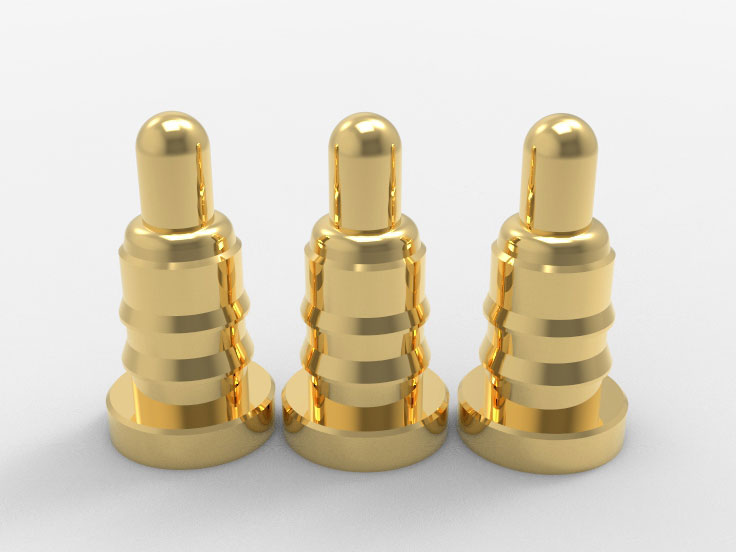
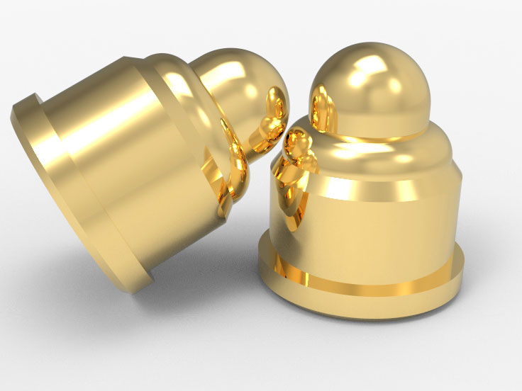
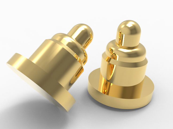
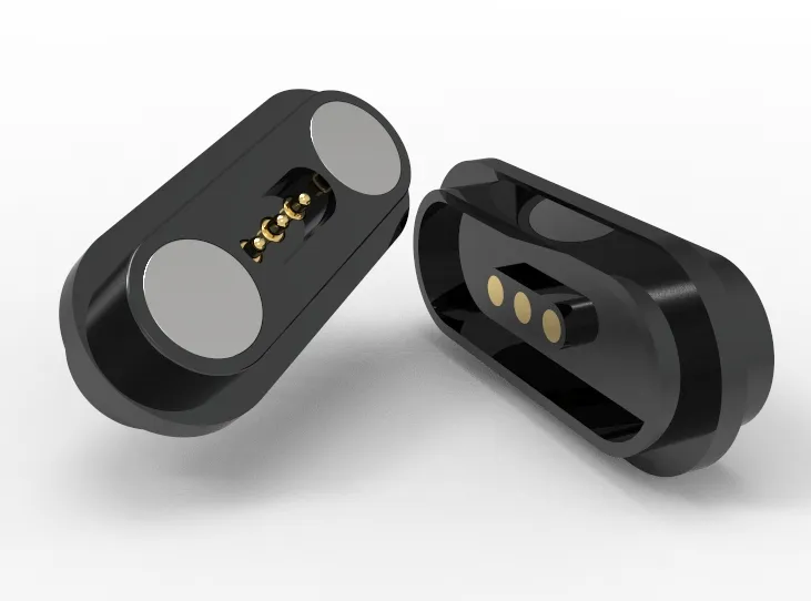
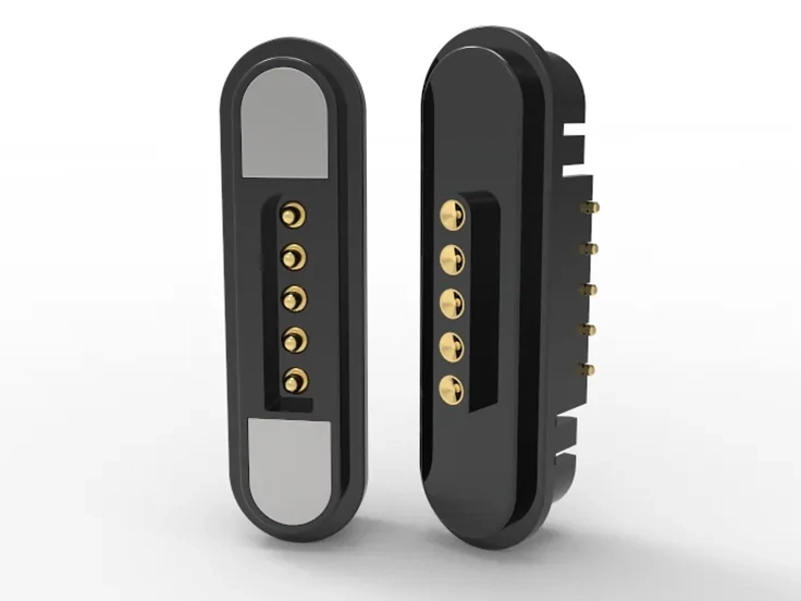
Plunger can provide various end types such as flat, pointed, cup, blade, spherical surface, anti-deflection inclined surface, and coating retention.
Contact materials and surface treatment:
Support the selection of multiple substrates such as Cu alloy, BeCu, SUS, nickel titanium alloy, etc. Surface treatment processes include hard gold, soft gold, nickel palladium gold, chemical nickel, composite coatings, etc. The thickness and distribution of the coating support parameterized definition.
Customization of carrier packaging and feeding method:
Support designing suction nozzles/positioning benchmarks according to customer specified mounting models. Provide 8mm/12mm bandwidth and 2/4/6 column installation. Support Tray disk Carrier Reel、 Blister tray, loose packaging with multiple packaging specifications.
Matching verification and sample co-research mechanism:
Support customer’s original working condition parameter modeling and sample co research. Can output 3D packaging diagram (STEP)+process tolerance window diagram + assembly suggestions. Used for downstream fixture/fixture tray/mounting program design.
Multi project parallel capability:
The engineering platform supports up to 12 parallel project design and sampling production processes. A typical response period of ≤3 days is required to output preliminary recommended solutions. Samples can be produced within 14 days, and all model numbers can be reused across stages.
Click: More Catalog
FAQ
Can mirco pogo pins meet the standard SMT mounting process and cause structural deformation during the Reflow process?
The barrel tail pin is a flat bottomed solder pad structure, matched with 8mm/12mm carrier tape and vacuum suction nozzle mounting requirements. Through JEDEC J-STD-020 welding thermal shock verification, there was no spring deformation or plating detachment after 3 cycles at 260℃. Mirco pogo pins are suitable for all mainstream reflow soldering processes.
What is the minimum center to center distance that can be achieved for multi pin connectors or FPC boards?
The standard minimum needle pitch is 1.00mm (Pitch). Under the condition of Pitch ≥1.00mm, the independent design of the spring chamber can still be maintained without electrical interference. Can be used in conjunction with the staggered structure of upper and lower pogo pins for high-density spatial connection design.
Does Mirco pogo pins have a structural design to prevent compression bias and inclination?
The needle can be equipped with a slanted anti deviation structure or a self-aligning ball head design. Capable of compensating for angles within ± 10° within the work travel range. If necessary, limit rings/stop columns can be added to assist in improving the stability after installation.
Can mirco pogo pins control the coating only in specific contact areas? How do mirco pogo pins ensure the reliability of the welding end?
Support selective plating process, with Ni/Au or Ni/Pd/Au plating on the contact end. The welding end is made of pure nickel or coated with gold, palladium, or platinum surface, ensuring both contact conductivity and welding wettability meet the standards. Avoid excessive electroplating affecting the quality of solder joints.
Can mirco pogo pins be sampled in parallel for multiple projects? Can the project promotion cycle be shortened?
Equipped with an independent engineering scheduling platform, mirco pogo pins supports up to 12 parallel projects. DFM review, 3D structure output, and production process path will be completed within 3 working days. The regular structure sample can be shipped within 48 hours at the fastest, meeting the scenario of synchronous promotion of multiple SKUs.
 +86 13590816656
 +86 13590816656