Johoty’s Services of Pogo Pin
Sample pogo pin: supports 3D drawings and real-time parameter quotation, and provides structural confirmation drawings within 48 hours. Satisfy engineering evaluation and reliability testing, and advance the NPI process without repeated communication.
Adaptation standards: tolerance for through-hole diameter error ± 0.03mm, insertion force control ±15gf. Tail length can be controlled to ±0.05mm, suitable for high-density board space design. Pogo pin is compatible with high-speed signals and high-current designs.
Quality control: Full batch automatic CCD appearance inspection, 100% displacement force value testing of crimping position. The thickness detection report of the electroplating layer can be traced back to the batch. Support life testing (>50K cycles)/salt spray/constant temperature and humidity/impact vibration/high-frequency performance report.
Pogo pin delivery time: CNC samples will be sent out within 72 hours, and standard customized structures will be delivered within 14 days. The earliest delivery time for the first batch of mass production is 14 days. Support concurrent design/mold flow analysis/mold processing execution.
Minimum Order Quantity (MOQ): Starting from 3 sets of pogo pin samples, minimum order for mass production ≥1K (specific details can be negotiated based on structural complexity). Support structural reuse and common mode customization strategies.
Logistics method: DHL/FedEx/UPS, default free shipping for samples (5-8 days in regions such as the United States/Germany/Japan). Bulk shipments can be coordinated with customers’ designated freight forwarders or assisted in DDP scheme evaluation.
Contact person qualification: Senior technical support engineer directly. More than 10 years of experience in pogo pin/high reliability pogo structure research and development background. English communication, with a basic understanding of MIL/IPC/J-STD standards.
Click: More Catalog
Performance Test of Pogo Pin
Contact resistance detection: 100% actual measurement record, initial contact impedance ≤50mΩ. Impedance change after full load crimping ≤10%, high-speed/high current/low loss transmission.
Life test: >10,000 reciprocating compression cycles, with a retention force attenuation of <15%. High frequency plug-in application, with high reliability of elastic structure.
Temperature rise test: Resistance heating temperature rise<20℃ under rated current (3.0A). The measured linear curve and temperature limit point are attached, suitable for safety assessment of continuous current carrying structures.
Insertion force and retention force: The standardized control range for insertion force is 20 gf, with a tolerance of ±5gf, ensuring controllable compression and rebound accuracy. Maintain a force test of ≥0.2N to verify the mechanical connection strength.
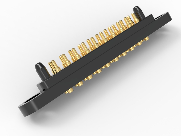
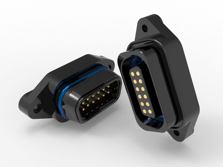
Stability verification of tail insertion: Simulate insertion into a 0.5-2.50mm through-hole, with a tail swing of less than 0.05mm. Support for automated plug-in and dimensional stability verification after reflow soldering.
Plating thickness and adhesion: Gold plating ≥3μ”/30μ” optional, Ni bottom layer ≥150μ”. Adhesion ≥1.1N/mm², coating consistency report issued with batch.
Environmental stress resistance verification: Salt spray test (24H/48H/96H), high and low temperature cycling (-40+85 ° C). Constant temperature and humidity (85 ° C/85% RH/168H), meeting medical/automotive/military reliability requirements.
Vibration and shock test: Three axis 6-hour sweep frequency vibration+50g mechanical shock, and the electrical performance remains consistent after testing. Johoty’s pogo pin is preferred for portable/in car/flight control applications with complex applications.
Material traceability and RoHS compliance: Pogo pin material HBi59/C3604 is selected as needed. The COA of supporting materials and third-party environmental reports can be traced back to the batch level.
Click: More Catalog

Customization of Pogo Pin
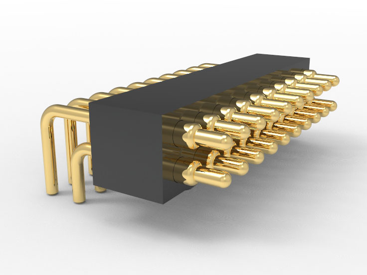
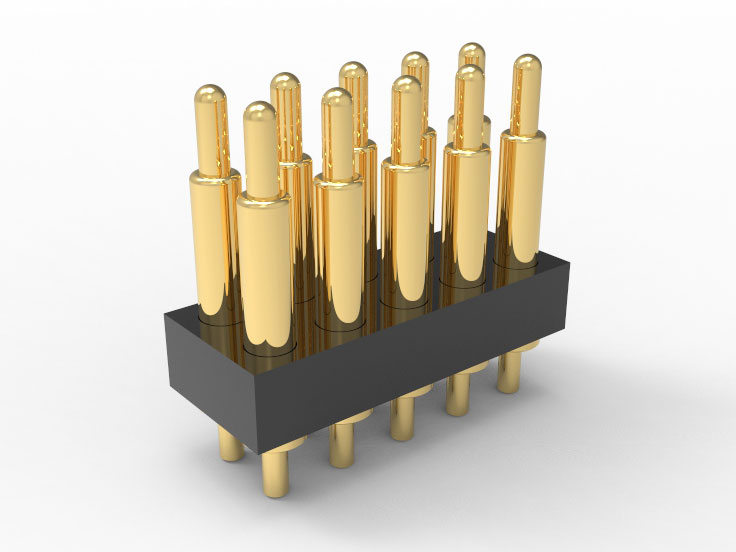
Customization range of tail structure: Supports customization of tail diameter ≥0.3mm, with a minimum tail length of 0.50mm. Tolerance control ±0.05mm, high-density through-hole insertion compatible with automation plugins.
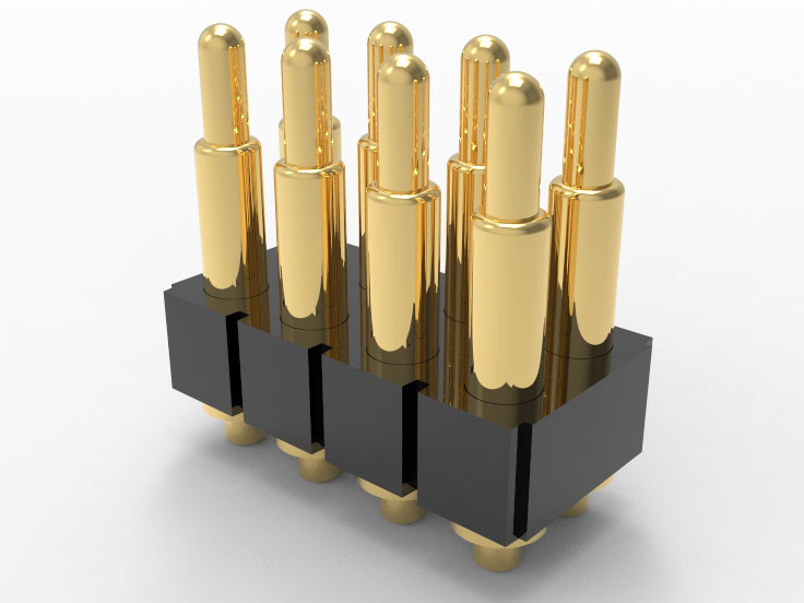
Total length control capability: Control the total length of pogo pin to <5.0mm, and flexibly customize space limited designs with compression stroke ≥0.10mm.
Spring force and stroke configuration: Supports custom springs ranging from 10gf to 200gf, with multiple compression stroke structures available. Flexible customization of different contact pressures and compression response curves.
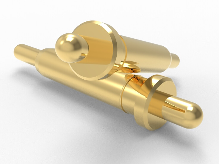
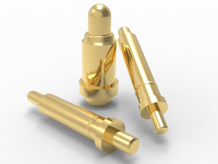
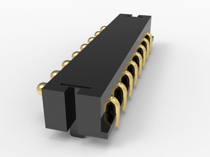
Tail guidance optimization: limit shoulders, chamfers, and slots can be designed to provide stable insertion guidance and improve the efficiency of through-hole fitting.
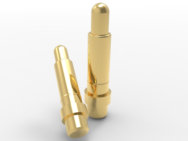
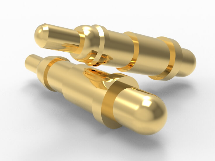
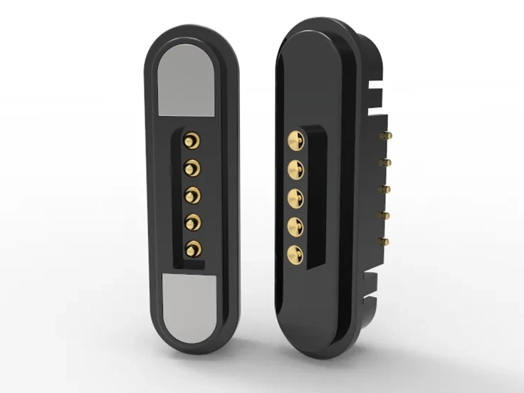
The shape of the plunger tip can be selected: hemispherical, conical, flat, oblique, or single plunger point, matching different pad shapes/pad areas/contact surface requirements.
Flexible selection of material combinations: Spring, barrel, plunger can be customized according to different materials (SWB-P, SK4, Beryllium Copper, SUS304, etc.). Match high frequency, high temperature, and corrosion resistance.
Electroplating process: Supports full or partial gold plating, electroplated silver/nickel/palladium/composite multilayer, with a gold layer thickness of 0.01 μ m~5 μ m (4 μ” ~ 200μ”) optional.
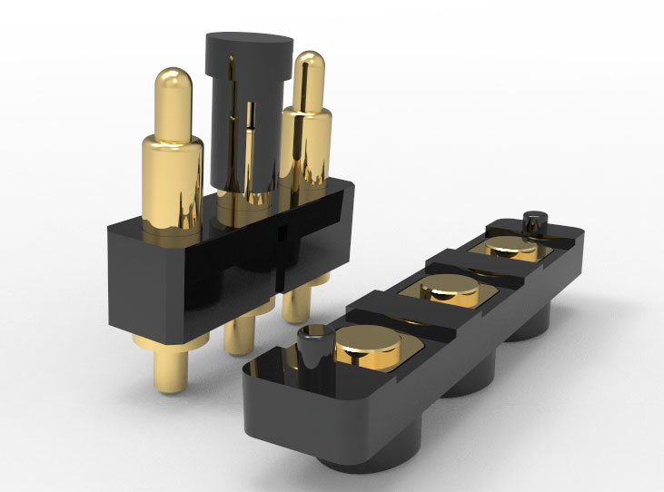
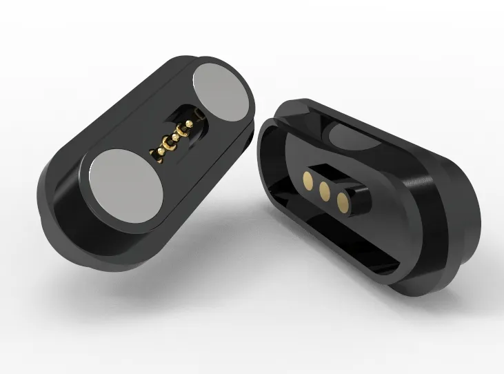
Collaborative structural common mode design: supports development in conjunction with positioning shells, plastic carriers, and FPC soldering sockets. Realize the integration of pogo pins and structural components to improve assembly efficiency.
Development response mechanism: Propose the structure within 1 day, confirm the sample plan within 3 days, and deliver customized samples within 14 days. Support DFM analysis and full lifecycle BOM coordination management.
Click: More Catalog
FAQ
Can pogo pin be stably inserted into a 0.90mm through-hole without affecting performance?
It can be achieved. The tail can be precision machined to 0.60mm ± 0.02mm, and it has a good interference fit with a 0.90mm ± 0.05mm through-hole design. The compression force and rebound performance are within the standard range, and the stability can be tested repeatedly by plugging.
Does pogo pin support size retention after reflow soldering/wave soldering?
Support. The tail design can add limit shoulders/positioning steps to effectively prevent high-temperature displacement. The material’s thermal expansion coefficient has been verified to match the PCB. High temperature treatment does not affect the stability of tail insertion.
Can pogo pins meet a compression stroke of 0.60mm while maintaining a total length of <5.00mm?
Bidirectional compression chambers or short stroke high-K spring structures can be designed as needed. Realize compression stroke of 0.5mm~0.6mm within a total length of 5.00mm, compatible with board to board/module docking.
Does pogo pin meet high-frequency signals or high current applications?
Satisfied. The measured contact impedance is less than 50mΩ, and the rated current supports a continuous current of 1-3A. Provide high-speed signal simulation support (S parameters, TDR curves, etc.), which can be used in conjunction with shielding shells for common ground optimization.
Can pogo pin customize supporting structures (positioning parts/housing) in parallel and assist in integrated design?
Executable. Support common mode development of integrated structural components (pogo pin + plastic positioning seat/FPC pressure plate). Internally, synchronous modeling and verification of assembly tolerances can be achieved, reducing the number of docking steps and improving overall assembly efficiency.
 +86 13590816656
 +86 13590816656